Jounce bumper

a bumper and jig technology, applied in the field of jigs, can solve the problems of not providing a positive stop to the system, not enough space to package a bumper, etc., and achieve the effect of increasing the bumper rate, increasing the amount of energy, and increasing the bumper ra

Inactive Publication Date: 2006-01-05
U S FARATHANE CORP
View PDF28 Cites 20 Cited by
  • Summary
  • Abstract
  • Description
  • Claims
  • Application Information

AI Technical Summary

Benefits of technology

[0008] In an alternative embodiment, the bumper with the insert is partially placed within a TPU cup attached to a surface of either a strut assembly or free standing in another assembly to increase the rate of the bumper. As a force acts upon the bumper, it begins to press into the TPU cup. Upon an increasing force being applied, the TPU cup begins to expand outwardly at its opening at the same time the bumper compresses within the TPU cup. Similarly to the previous embodiment, the insert will limit inward movement of the bumper, however, the flexibility of the thermoplastic urethane will allow the insert to move a little as a result of the movement inward and absorb a po

Problems solved by technology

In most cases, there is not enough space to package a bumper large enough to absorb the amount of energy experience durin

Method used


Image

  • Jounce bumper
  • Jounce bumper
  • Jounce bumper

Examples


first embodiment

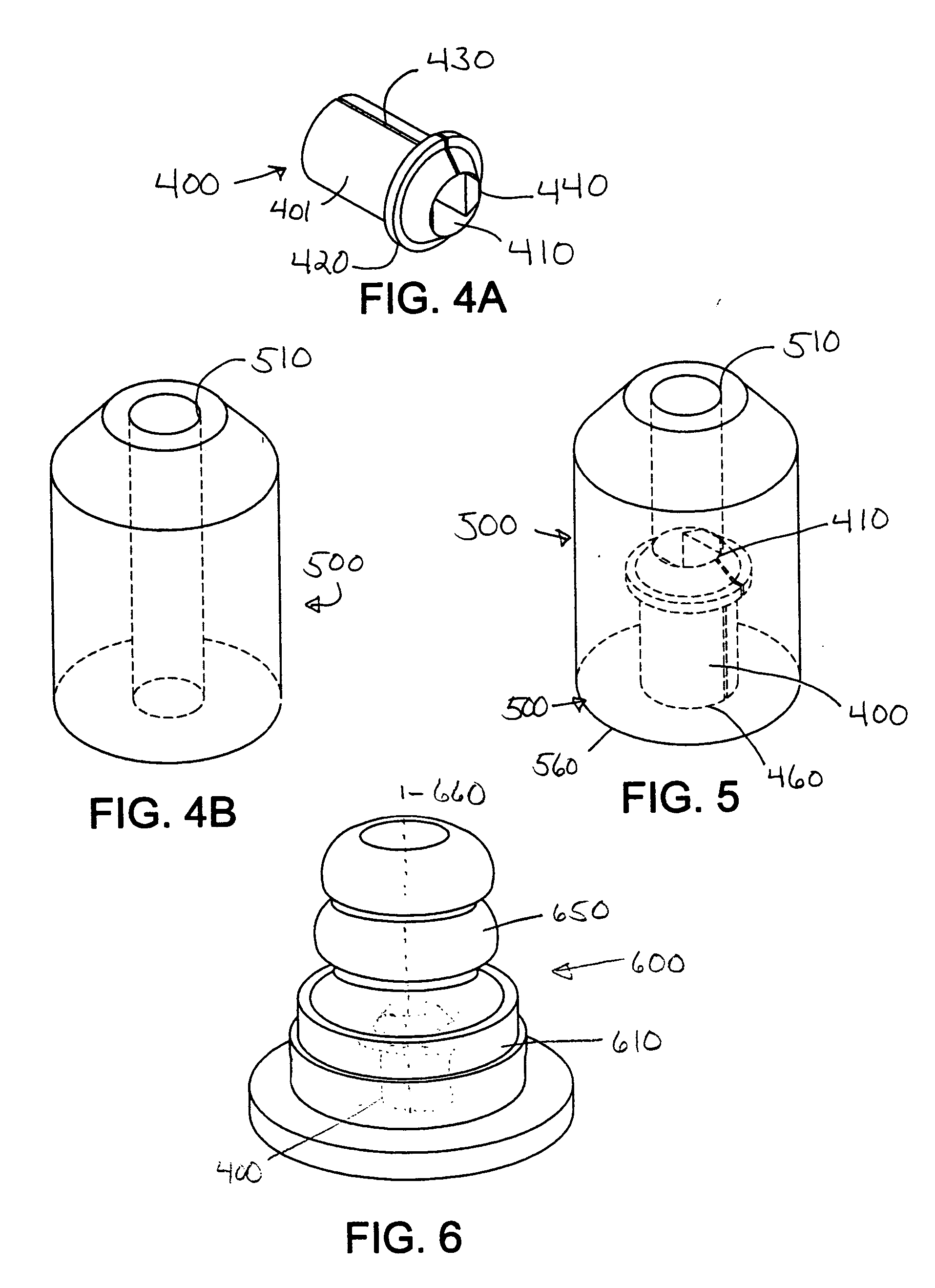
[0023] A parts view of the jounce bumper assembly according to the invention is shown in FIGS. 4A and 4B and the assembled view is shown in FIG. 5. The same reference numerals will be used for the same parts in different views. The insert is shown in FIG. 4A. As shown, the insert 400 generally comprises a cylindrical shape having a longitudinal hole 410 that has a diameter D along its length thereof. An annular flange portion 420 is provided around the outer surface 401 of the insert 400. The flange 420 is shown near an upper side 440, however, it may be at any position along the length of the insert 400. Its use and operation will be described below. The insert 400 may also have a slit 430 along its length thereof to allow for expansion of the diameter of the hole 410. The insert 400 may also have flat sides 450 along the inner surface of the hole 410, which can be used in operation to prevent the insert from rotating about a shaft on which it may be mounted. However, these surface...

second embodiment

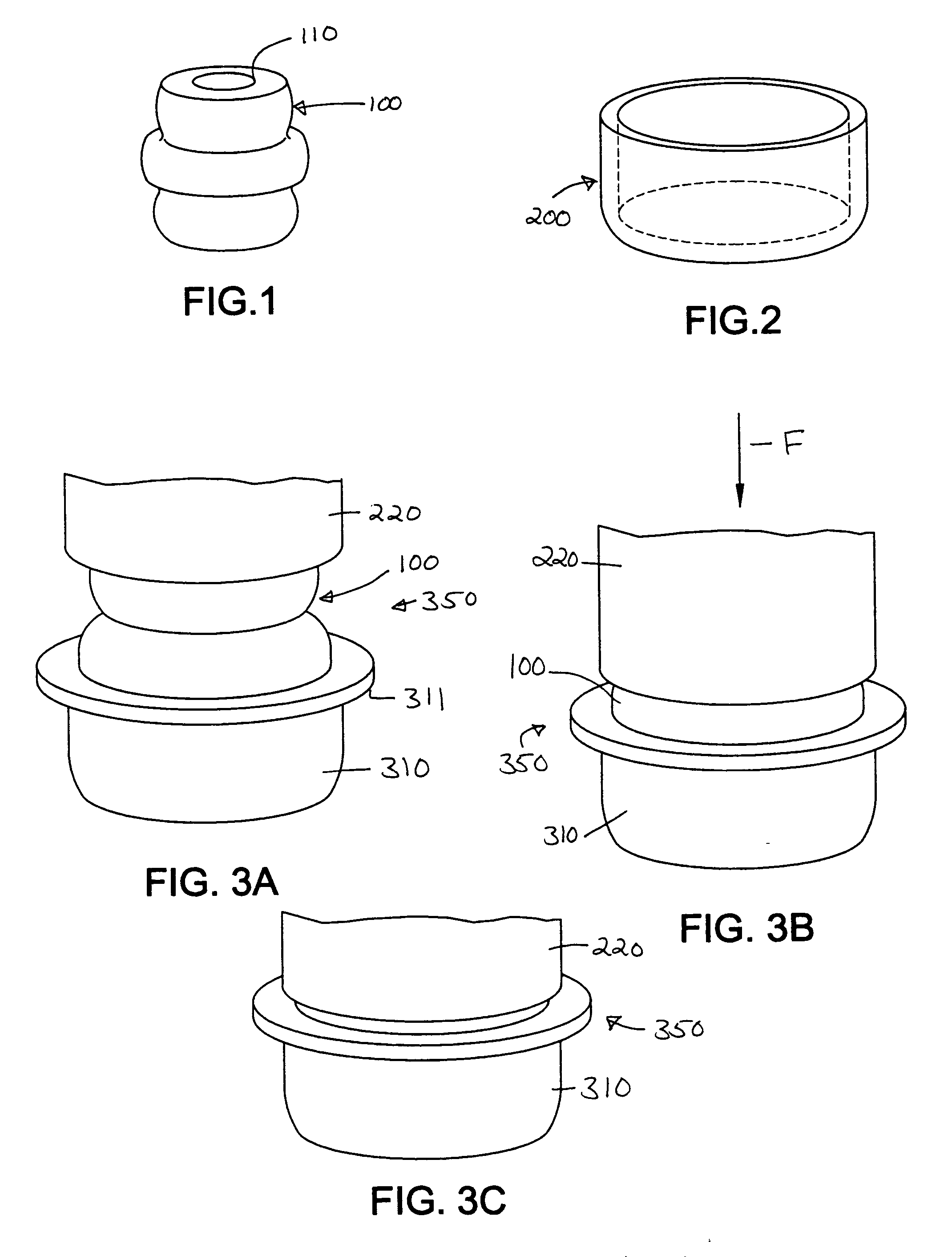
[0030] a bumper assembly 600 according to the invention is shown in FIG. 6, wherein the combination of a bumper 650 having an insert 400 mounted therein is partially inserted into a cup 610. The cup may be either a metal or a plastic cup. For purposes of this embodiment a thermoplastic urethane (TPU) cup was used. Such material is well known as described above. The cup 610 generally has a cavity 611 along its central axis for receiving a portion of the bumper 650, as shown.

[0031] The placement of bumper assembly 600 between objects 710 and 720, as shown in FIG. 8A, provides similar actions, but different results because of the cup 610. As shown in FIG. 8B, a force acts upon object 720 in the direction F towards object 710. This begins to compress bumper 650 into the cavity 611 of the cup 610. As the force continually compresses the bumper 650, the bumper begins to expand slightly outward from its longitudinal axis 660 and inward toward the axis. As the bumper 650 compresses around t...

third embodiment

[0032] As a third embodiment to that shown in FIGS. 6, 8A-C, the cup could be made of metal or a non-flexible plastic or other material. This would have the effect of completely resisting the outward expansion of the bumper 650, but would otherwise operate in a similar manner. The reduction in the outward expansion of the bumper 650 as a result of the rigid cup and the use of the insert 400 has the effect of reducing the overall compression of the bumper assembly in comparison with the bumper assembly 650 having a flexible cup 610.

[0033] A comparison of various combinations of bumpers, inserts and cups is illustrated in FIG. 10. The graph shows a how much the bumper assembly will compress under a force of 10,000N. Four bumper assemblies were compared, a bumper with no insert, a bumper with an insert, a bumper mounted inside a rigid cup and a bumper with an insert mounted inside the cup. For each assembly, a similar bumper was used, as well as a similar insert and similar cup.

[0034]...


PUM


Abstract

An energy absorption device for providing a softer stop arrangement between a pair of components. A bumper is provided with a cylindrical insert mounted therein. Upon application of force between the components, the compressible bumper collapses around the insert and outward. The insert prevents the bumper from expansion inward of the bumper to limit the amount the bumper compresses and further is made of a flexible material to absorb energy. The combination of the bumper and the insert provides a definite stop to the bumper assembly. The device is usable between any two components to prevent collisions between the components up to a certain force between them and is also usable between a strut assembly and a vehicle suspension to prevent the strut assembly from bottoming out.

Description

[0001] This invention relates to a jounce bumper for motor vehicle suspensions systems either in the strut assemblies or other locations. BACKGROUND OF INVENTION [0002] Microcellular urethane bumpers are used in vehicle suspensions to absorb energy during jounce and to act as a supplemental spring. The bumper 100 has a general appearance as shown in FIG. 1. These could be mounted on a strut assembly, as shown in the U.S. Pat. No. 5,487,535, where the bumper surrounds the piston rod of the strut. A hole 110 through bumper 100 allows for passage of the piston rod. This bumper prevents the cylinder of the strut assembly from impacting heavily the mounting assembly. The bumpers could also be mounted in other locations, as shown in U.S. Pat. No. 5,725,203, where the bumper is free standing to prevent a control arm of the suspension from impacting with the vehicle frame. [0003] Bumpers can be mounted in a free state or within a rigid cup, as shown in U.S. Pat. No. 6,158,726, which disclos...

Claims


Application Information

Patent Timeline
IPC IPC(8): F16F3/08
CPCF16F1/371F16F3/093F16F1/44
Inventor RAZA, IRFAN
Owner U S FARATHANE CORP
Why Eureka
Try Eureka