Segment for a rehabilitating pipe

a rehabilitating pipe and segment technology, applied in water installations, sewer systems, construction, etc., can solve the problems that water tightness cannot be guaranteed in the coupling part, and achieve the effect of improving water tightness in the coupling surface, sufficient water tightness, and excellent

Active Publication Date: 2006-01-05
SHONAN GOSEI JUSHI SEISAKUSHO KK
View PDF12 Cites 8 Cited by
  • Summary
  • Abstract
  • Description
  • Claims
  • Application Information

AI Technical Summary

Benefits of technology

[0010] The structure of the present invention improves the watertightness in the coupling surfaces in the longitudinal direction of the rehabilitating pipe and can ensure sufficient watertightness because, when mutually coupling the segments in the longitudinal direction of the rehabilitating pipe, the protruding part and the recessed part of one of the coupling surfaces of one of the segments in the longitudinal direction is brought into tight surface contact and can be interfitted with the recessed par

Problems solved by technology

Nevertheless, in the structure of the conventional segment 1 as described above, there is a problem in that watertightness can sometimes not be ensured in the coupling part because, in the state wherein the segments 1 are mutually coupled by fitting the protruding p

Method used


Image

  • Segment for a rehabilitating pipe
  • Segment for a rehabilitating pipe
  • Segment for a rehabilitating pipe

Examples


Embodiment Construction

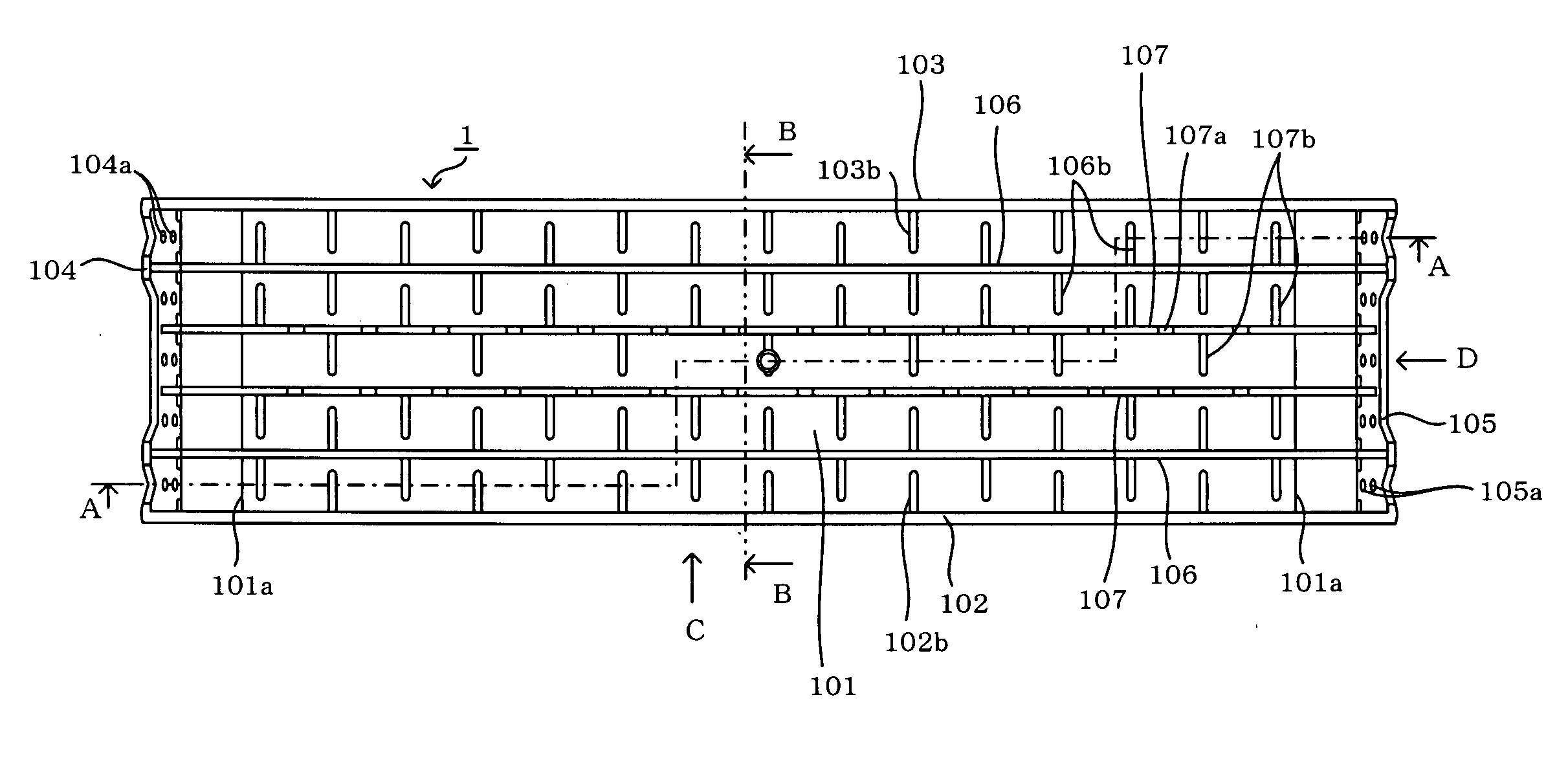
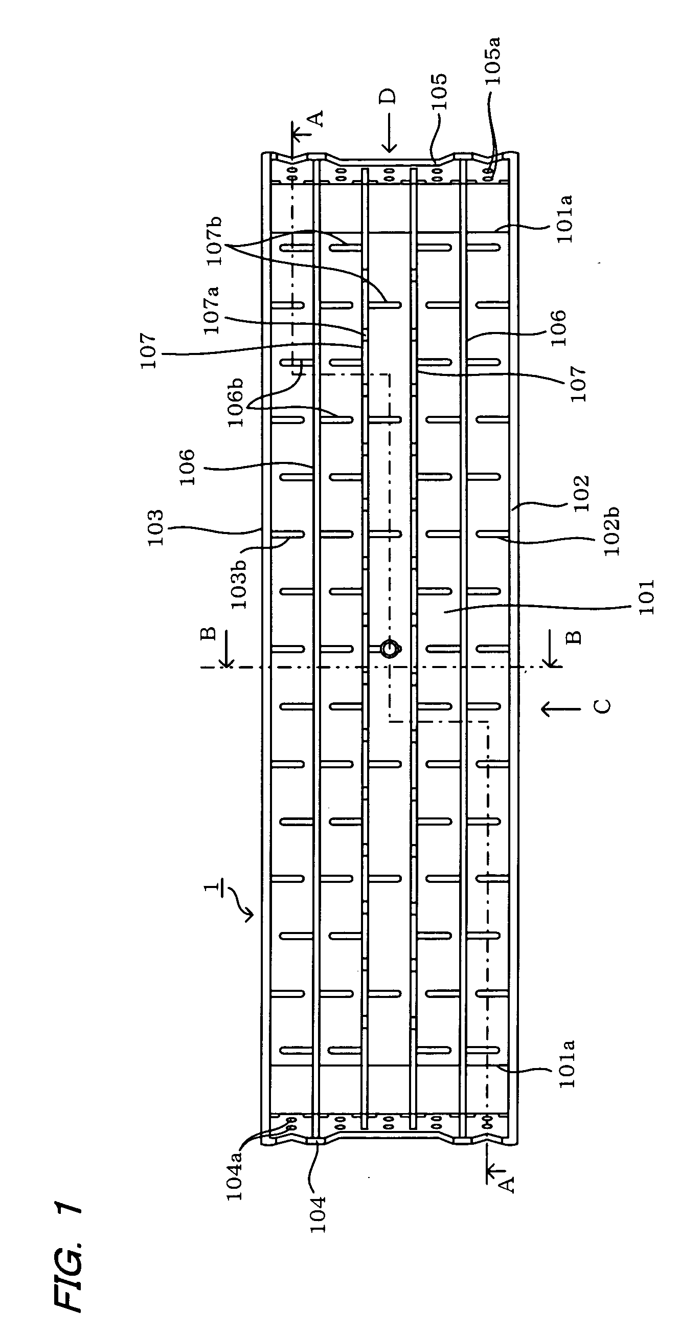
[0026] The invention will be described based on embodiments, referring to the drawings. To rehabilitate the existing pipe, such as a sewer pipe, segments are used to assemble a circular, ring-shaped pipe unit 2. One segment corresponds to one piece of the pipe unit 2 when it is divided for segmentation into a plurality of equal parts in the circumferential direction, e.g., five equal parts. The pipe unit 2 is assembled by coupling a plurality of segments 1 in the circumferential direction of the rehabilitating pipe 3, and these are successively coupled in the longitudinal direction to assemble the rehabilitating pipe 3.

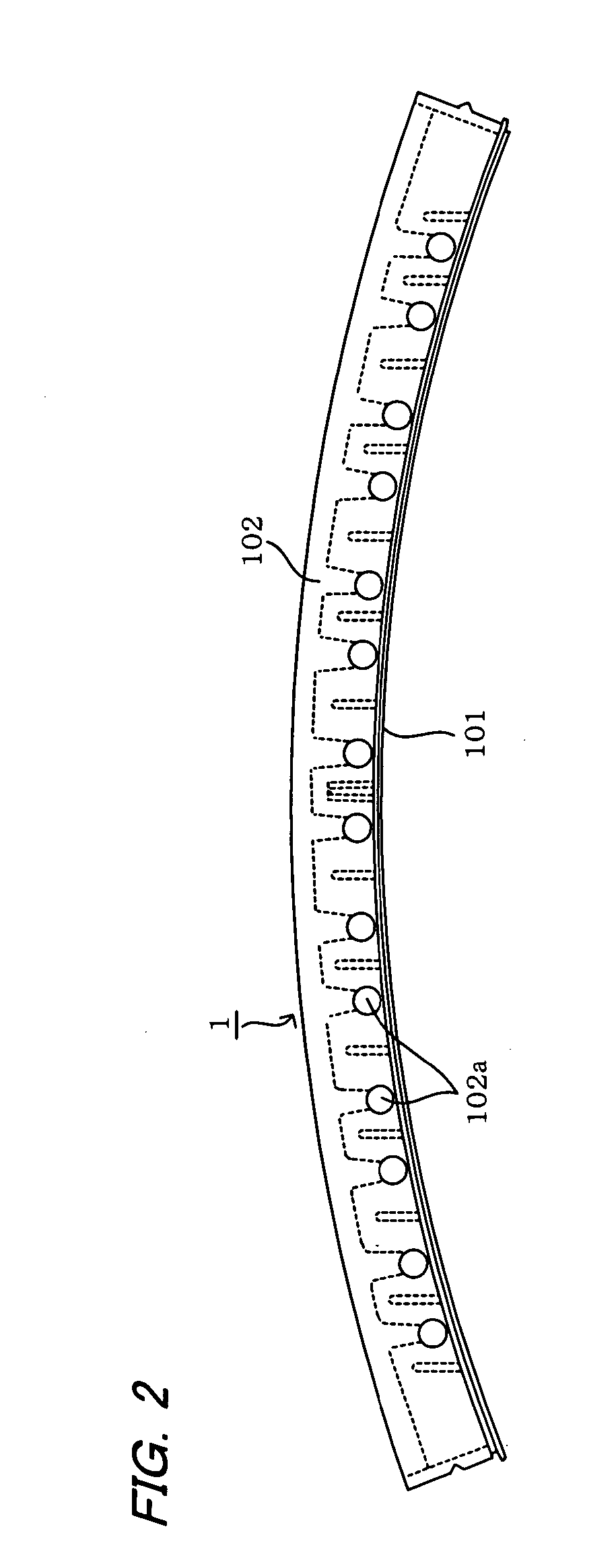
[0027]FIG. 1 through FIG. 6 explain the structure of the segment 1 of the present embodiment. FIG. 1 is a top view of the entire segment 1. FIG. 2 is a side view viewed in the arrow C direction in FIG. 1. FIG. 3 is a cross-sectional view taken along the A-A line in FIG. 1. FIG. 4 is a bottom view of the segment 1. FIG. 5 is an auxiliary view viewed in the arrow D dir...


PUM


Abstract

A segment for a rehabilitating pipe is coupled to another segment in the circumferential and longitudinal directions of a rehabilitating pipe to rehabilitate an existing pipe. The segment has on one coupling surface a protruding part and a recessed part continuous with the protruding part and on another coupling surface a recessed part and a protruding part whose shapes respectively conform to the protruding part and the recessed part of one coupling surface. The protruding part and the recessed part of one coupling surface of one segment is brought into tight surface contact with the recessed part and protruding part of another coupling surface of another segment and interfitted thereto when one and another segments are mutually coupled in the circumferential and longitudinal directions of the rehabilitating pipe.

Description

BACKGROUND OF THE INVENTION [0001] 1. Field of the Invention [0002] The present invention relates to a segment adapted for use for a rehabilitating pipe that is assembled to rehabilitate an existing pipe, such as a sewer pipe. [0003] 2. Description of the Prior Art [0004] A method of rehabilitating an existing pipe is known from Japanese Patent Laid Open Publication No. 2003-214098 and the like, wherein a compound pipe is constructed to rehabilitate an existing pipe like a sewer pipe by, as shown in FIG. 11, assembling inside an existing pipe 4 a rehabilitating pipe 3 whose outer diameter is slightly less than the inner diameter of the existing pipe 4, and then filling and hardening a filler (not shown) in the gap between the outer periphery of the rehabilitating pipe 3 and the inside wall surface of the existing pipe 4. The rehabilitating pipe 3 is assembled using segments. Namely, as shown in FIG. 12, the rehabilitating pipe 3 is assembled by an assembly worker S who couples insid...

Claims


Application Information

Patent Timeline
IPC IPC(8): F16L55/00F16L1/00E03F7/00F16L55/162F16L55/165
CPCF16L55/1657
Inventor KAMIYAMA, TAKAOKANETA, KOJIFUJII, KENJIISHIDA, MAKOTO
Owner SHONAN GOSEI JUSHI SEISAKUSHO KK
Why Eureka
Try Eureka