
System and method for design of projector lamp

a projector lamp and projector technology, applied in the field of lighting systems, can solve the problems of residual potential stresses and sealing cracks are particularly problematic, and may arise various stresses due to the sealing process

Inactive Publication Date: 2006-01-05
GENERAL ELECTRIC CO
View PDF30 Cites 48 Cited by
  • Summary
  • Abstract
  • Description
  • Claims
  • Application Information

AI Technical Summary

Problems solved by technology

In either case, various stresses may arise due to the sealing process, the interface between the joined components, and the materials used for the different components.
For example, the component materials may have different mechanical and physical properties, such as different coefficients of thermal expansion (CTE), which can lead to residual stresses and sealing cracks.
These potential stresses and sealing cracks are particularly problematic for high-pressure lamps.
Other components of the lamp further complicate the assembly of the lamp, and can further degrade the sealing and structural characteristics of the lamp.
Unfortunately, this complicates the sealing process for the lamp.
Unfortunately, it is relatively difficult to mount the arc electrode at the desired location on the end structure.
Moreover, existing mounting techniques may involve the application of heat, which can cause stress cracks in the lamp and can embrittle the arc electrode.

Method used


Image

  • System and method for design of projector lamp
  • System and method for design of projector lamp
  • System and method for design of projector lamp

Examples


Embodiment Construction

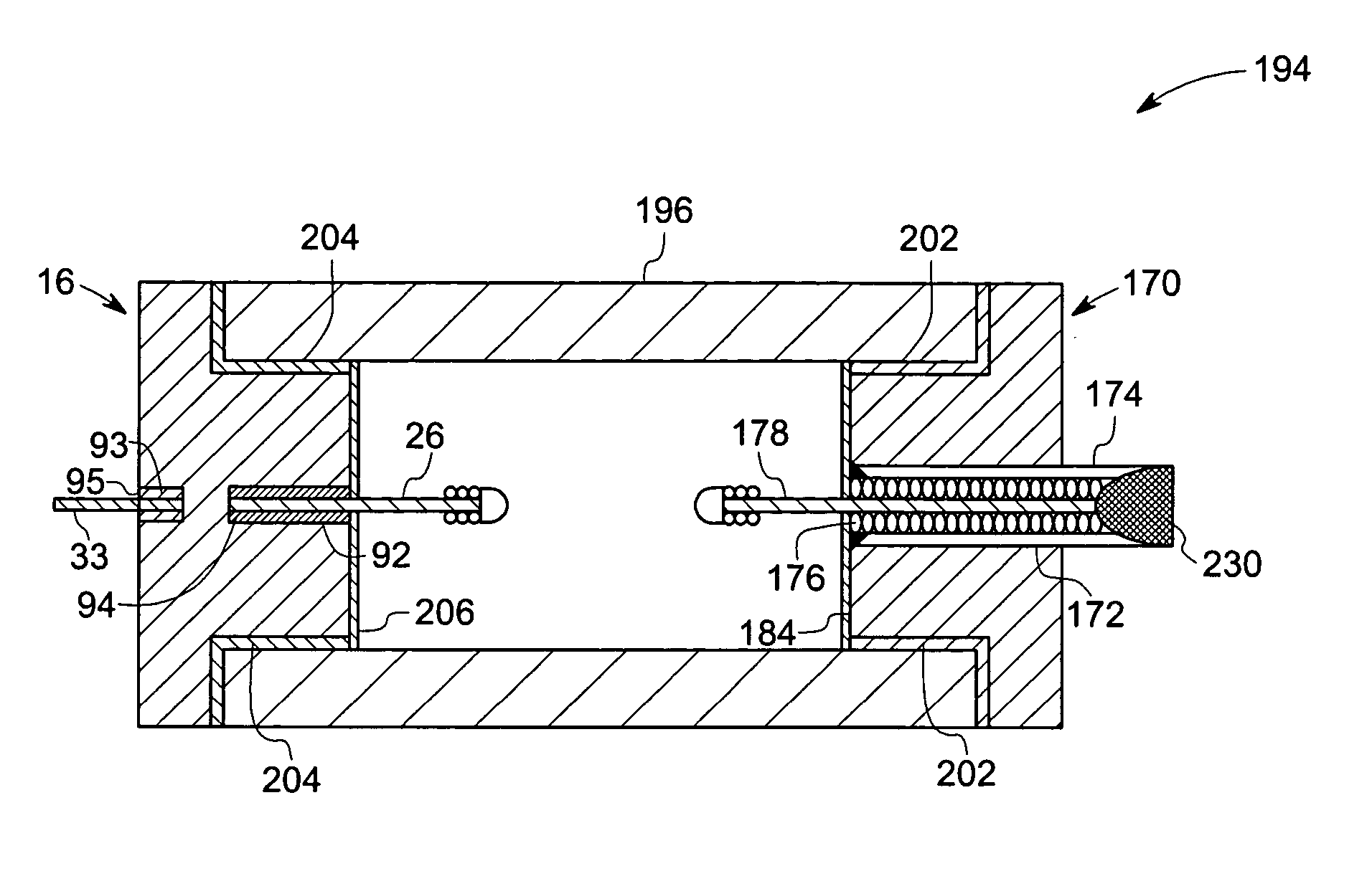
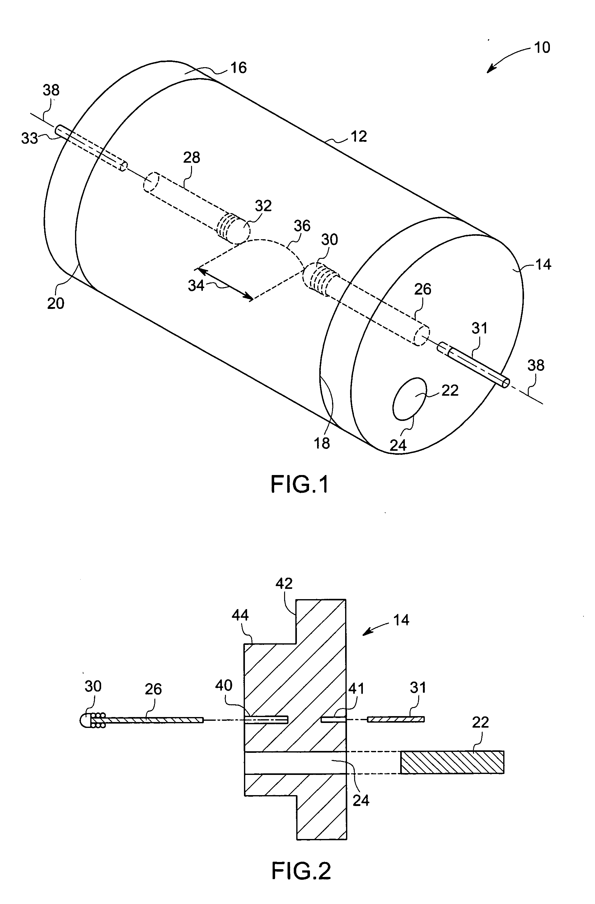
[0024] Turning now to the drawings, FIG. 1 is a perspective view of an exemplary lamp 10 in accordance with certain embodiments of the present technique. As illustrated, the lamp 10 comprises a hermetically sealed assembly of a hollow body or arc envelope 12 and end structures 14 and 16 coupled to opposite ends 18 and 20 of the arc envelope 12. These and other components of the lamp 10 are formed from a variety of materials, which are either identical or different from one another. For example, different embodiments of the arc envelope 12 are formed from a variety of transparent ceramics and other materials, such as yttrium-aluminum-garnet, ytterbium-aluminum-garnet, microgram polycrystalline alumina (μPCA), alumina or single crystal sapphire, yttria, spinel, and ytterbia. Other embodiments of the arc envelope 12 are formed from conventional lamp materials, such as polycrystalline alumina (PCA). Turning to the end structures 14 and 16 of the lamp 10, these components are formed from...


PUM


Abstract

A lamp comprising an arc envelope and an end structure coupled to the arc envelope, and wherein the end structure comprises at least one opening adapted to support an arc electrode and to receive a dosing material into the arc envelope.

Description

BACKGROUND [0001] The invention relates generally to the field of lighting systems and, more particularly, to high-intensity discharge (HID) lamps. Specifically, embodiments of the present technique include a hermetically sealed lamp having improved dosing, sealing, and electrode mounting features. [0002] High-intensity discharge lamps are often formed from a ceramic tubular body or arc tube that is sealed to one or more end structures. The end structures are often sealed to this ceramic tubular body using a seal glass, which has physical and mechanical properties matching those of the ceramic components and the end structures. Sealing usually involves heating the assembly of the ceramic tubular body, the end structures and the seal glass, to induce melting of the seal glass and a reaction with the ceramic bodies to form a strong chemical and physical bond. The ceramic tubular body and the end structures are often made of the same material, such as polycrystalline alumina (PCA). How...

Claims


Application Information

Patent Timeline
IPC IPC(8): H01J5/48H01J5/50H01J9/00
CPCH01J9/395H01J9/40H01J61/82H01J61/366H01J61/363
Inventor VARTULI, JAMES SCOTTTEDESCHI, STEPHEN THOMASEMILIANA LORIO, LUANAKNUDSEN, BRUCE ALANERIKSON, CARL EDWARDBREWER, JAMES ANTHONYWHARMBY, DAVID OSBORNBEWLAY, BERNARD PATRICK
Owner GENERAL ELECTRIC CO
Learn More