Plasma display panel

a technology of display panel and plasma, which is applied in the manufacture of electrode systems, electrode discharge tubes/lamps, and electrodes, etc., can solve the problems of increasing manufacturing costs, increasing manufacturing costs, and lowering the opening ratio of the panel

Inactive Publication Date: 2006-01-05
SAMSUNG SDI CO LTD
View PDF5 Cites 21 Cited by
  • Summary
  • Abstract
  • Description
  • Claims
  • Application Information

AI Technical Summary

Benefits of technology

[0012] In accordance with the present invention, a plasma display panel capable of guiding...

Problems solved by technology

As such, according to the conventional approach the work process is very complicated and thus, the cost of manufacturing the panel increases.
Further, since the transparent electrode is expensive, this also increases the manufacturing cost.
While manufacturing cost can be reduced as compared to the above-mentioned str...

Method used


Image

  • Plasma display panel
  • Plasma display panel
  • Plasma display panel

Examples


Embodiment Construction

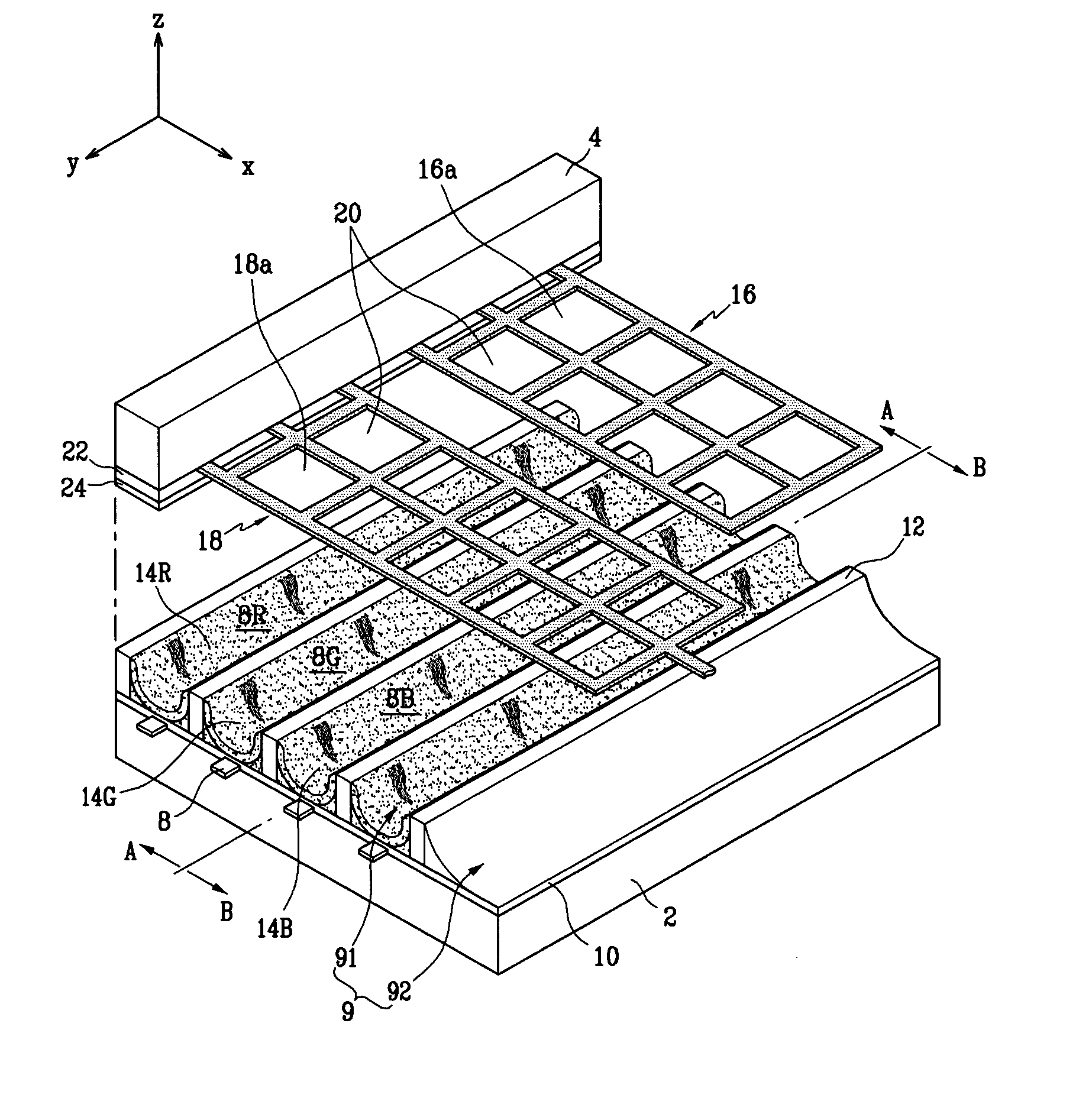
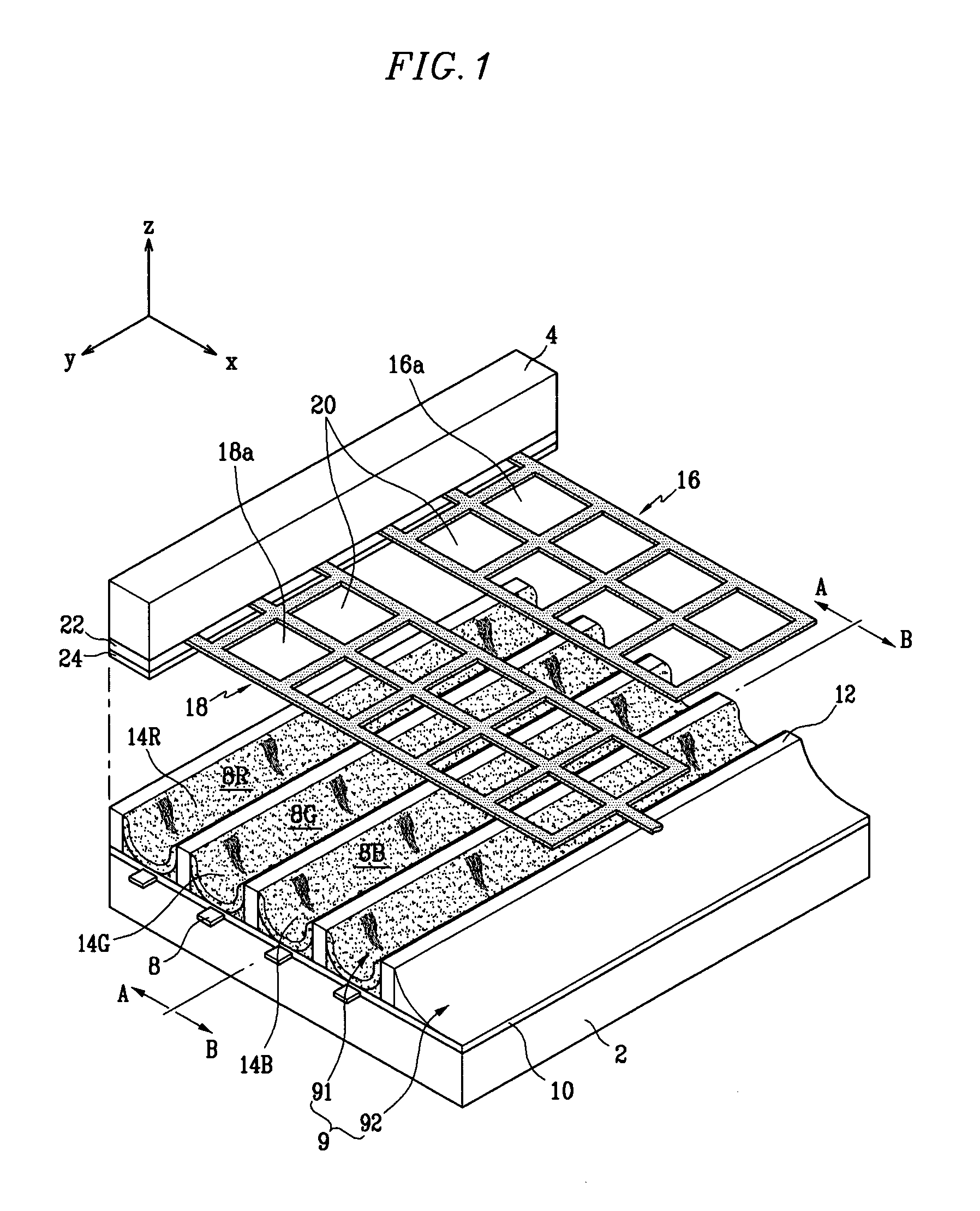
[0026] Referring to FIG. 1, the PDP according to the present embodiment has a structure such that a pair of substrates 2 and 4 are disposed opposite to each other at a predetermined gap, and discharge cells 8R, 8G, and 8B corresponding to red (R), green (G), and blue (B) cells defined by barrier ribs 12 are provided between the pair of substrates. Address electrodes 8 are arranged along a width-wise direction (an X-axis direction in FIG. 1) of each of the discharge cells 8R, 8G, and 8B at a predetermined gap between adjacent address electrodes.

[0027] The address electrodes 8 are provided along a Y-axis direction on the substrate 2. Dielectric layer 10 is formed over the entire surface of the substrate 2 so as to cover the address electrodes 8.

[0028] The barrier ribs 12 are formed on the dielectric layer 10, and phosphor layers 14R, 14G, and 14B corresponding to red (R), green (G), and blue (B) layers are formed over surfaces of the barrier ribs 12 and the dielectric layer 10. Each...


PUM


Abstract

A plasma display panel includes a pair of substrates that are arranged opposite to each other, each having a display region to display an image and a non-display region not to display an image. Barrier ribs are located in a space between the substrates for forming a plurality of discharge cells. Phosphor layers are formed in the discharge cells. Address electrodes are formed on one of the substrates. First and second electrodes are formed on the other substrate so as to extend in a direction orthogonal to the address electrodes and are spaced apart from each other to form discharge gaps in the discharge cells. The first and second electrodes extend into the non-display region with different lengths from each other.

Description

CROSS-REFERENCE TO RELATED APPLICATION [0001] This application claims priority to and the benefit of Korean Patent Application 10-2004-0050675 filed in the Korean Intellectual Property Office on Jun. 30, 2004, the entire content of which is incorporated herein by reference. BACKGROUND OF THE INVENTION [0002] 1. Field of the Invention [0003] The present invention relates to a plasma display panel (PDP), and more particularly, to a PDP capable of improving the electrode structure to increase the brightness and of stabilizing charge. [0004] 2. Description of the Related Art [0005] A PDP is a display in which discharge cells and a pair of sustaining cells provided so as to correspond to each discharge cell are arranged between a pair of substrates, and phosphors corresponding colors including R (red), G (green), and B (blue) are excited with ultraviolet rays generated in the process of plasma discharge to display images. [0006] Typically, a display electrode is composed of a transparent...

Claims


Application Information

Patent Timeline
IPC IPC(8): H01J17/49H01J11/12H01J11/22H01J11/24H01J11/26H01J11/32H01J11/34H01J11/46
CPCH01J11/12H01J2211/245H01J11/24
Inventor JANG, TAE-WOONG
Owner SAMSUNG SDI CO LTD
Why Eureka
Try Eureka