Fractional divider system and method

a fractional divider and divider technology, applied in the field of fractional divider systems, can solve the problem of effective zero jitter, and achieve the effect of reducing timing error and small total timing error

Inactive Publication Date: 2006-01-05
INTEL MOBILE COMM GMBH
View PDF6 Cites 4 Cited by
  • Summary
  • Abstract
  • Description
  • Claims
  • Application Information

AI Technical Summary

Benefits of technology

[0028] An advantage with the method for reducing timing error at wakeup for low-power timer according to the present invention is that the timing jitter due to the method can be reduced to 1.5 high speed clock cycles, i.e., a small fraction of a microsecond. This means that the jitter is effectively zero compared to other sources of error, e.g., drift in the reference clock frequency.
[0029] A further advantage is achieved in accordance with another embodiment of the invention if the method also comprises counting the number of high speed clocks from the ideal timing reference to the first pulse of the low-power reference clock, and adjusting the preload value such that the late start of the measurement is compensated for.
[0030] A further advantage is achieved if the method also comprises exiting the low-power mode, either due to the expiration of a wake-up time means, or due to an external signal requesting wake up.
[0031] A further advantage is achieved if the method also comprises dividing the reference clock with an integer division ratio of either M or M+1.
[0032] A further advantage is achieved if the method also comprises selecting the integer division ratio in such a way to keep the total timing error as small as possible while being positive.
[0033] A further advantage is achieved if the current timing error is denoted k, and the number of cycles of the high speed clock required for the value k is given as: nHS=kX⁢TLPPDIV⁢THS

Problems solved by technology

This means that the jitter is effectively zero compared to other sources of error, e.g., drift in the reference clock frequency.

Method used


Image

  • Fractional divider system and method
  • Fractional divider system and method
  • Fractional divider system and method

Examples


Embodiment Construction

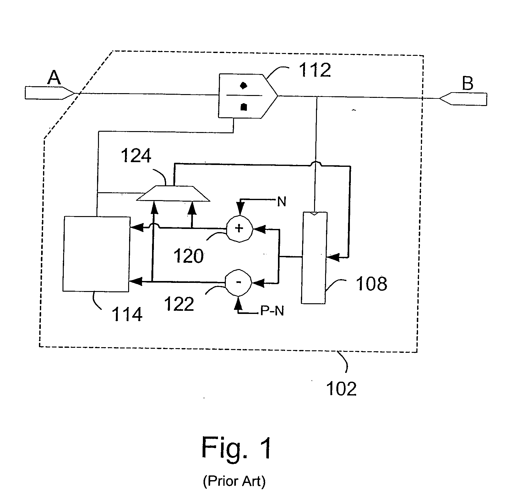
[0043] In FIG. 3 there is disclosed a block diagram of a fractional divider system 100 for a low-power timer with reduced timing error at wakeup according to the present invention. The fractional divider system 100 comprises a fractional divider circuit 102 operable to produce an output signal B with a frequency FC with the following relation to a reference clock frequency FLP: FLP=(M+NPDIV)×FC

wherein PDIV is the period of the fractional divider circuit 102, M is the integer part of the division ratio, and N is the magnitude of the fractional part of the division ratio. The input signal to the fractional divider circuit 102 is denoted A. The fractional divider system 100 also comprises a high speed crystal oscillator connected to the fractional divider circuit 102 operable to start on wakeup from the low power mode. The fractional divider system 100 also comprises a high speed clock divider circuit 106 connected to the fractional divider circuit 102 and to the high speed crystal o...


PUM


Abstract

The present invention relates to a fractional divider system for a low-power timer with reduced timing error at wake-up. The fractional divider system includes a fractional divider circuit operable to produce an output signal. The fractional divider system also includes a high speed crystal oscillator connected to the fractional divider circuit operable to start on wake-up from the low power mode, and a high speed clock divider circuit connected to the high speed crystal oscillator circuit. The high speed crystal oscillator circuit is configured to sample the output signal and a current state of the total timing error from the fractional divider circuit. The sampled output signal is employed to trigger the high speed clock divider circuit and the sampled current state of the total timing error preloads the high speed clock divider circuit, which is operable to synchronize a first pulse of the output signal to the ideal clock timing to an accuracy within 1.5 periods of the high speed clock.

Description

REFERENCE TO RELATED APPLICATIONS [0001] This application claims the benefit of the priority date of European patent application EP 04 015 423.9, filed on Jun. 30, 2004, the contents of which are herein incorporated by reference in their entirety. FIELD OF THE INVENTION [0002] The present invention relates to a fractional divider system for a low-power timer with reduced timing error at wakeup, and to a method for reducing timing error at wakeup for a low-power timer. BACKGROUND OF THE INVENTION [0003] Low power devices are often designed such that they exploit periods of inactivity to deactivate non-necessary functions and enter an “idle” mode. For instance, it is common to deactivate the high speed crystal oscillator (operating at 10s of MHz) that provides the timing reference for the digital and also possibly analogue components. This reduces the power consumption of the device dramatically. [0004] In many cases, it is necessary to be able to maintain an accurate timing reference...

Claims


Application Information

Patent Timeline
Patent Type & Authority Applications(United States)
IPC IPC(8): H03B5/32
CPCH03K23/68
Inventor LEWIS, MICHAEL
Owner INTEL MOBILE COMM GMBH
Why Eureka
Try Eureka