Systems and methods for automated resonant circuit tuning

a technology of automatic resonant circuit and tuning system, which is applied in the direction of electrial characteristics varying frequency control, instruments, calibration apparatus, etc., can solve the problems of difficult separation and quantification of enantiomers, inability to detect pharmacologically relevant levels of enantiomeric impurities in many desired modern pharmaceuticals, and inability to meet the increasing demands for rapid, high-sensitivity analysis

Inactive Publication Date: 2006-01-05
GIBBS PHILLIP R
View PDF26 Cites 172 Cited by
  • Summary
  • Abstract
  • Description
  • Claims
  • Application Information

AI Technical Summary

Benefits of technology

[0012] According to one aspect of the present invention, a method is described for automated tuning of a resonant circuit when detecting a chiral property of a sample. The method begins by populating a data structure with a plurality of frequencies. The plurality of frequencies may be pre-determined within an expected range of frequencies for the resonant circuit. A driving signal is then generated using one of the plurality of frequencies in the data structure. Next, the method applies the driving signal to the resonant circuit while detecting a chiral property of the sample, such as the Verdet constant, based at least in part upon the one of the plurality of frequencies in the data structure. A feedback signal is then measured, where the feedback signal is associated with a parameter (e.g., current) of the driving signal. Finally, the driving signal is adjusted to use another one of the plurality of frequencies in the data structure in response to the feedback signal. In this way, a resonant condition with the resonant circuit may be created.

Problems solved by technology

However, unlike other stereoisomers, enantiomers are often difficult to separate and quantitate.
However, analytical methods for assaying enantiomeric purity have not kept pace with the increasing demands for rapid, high sensitivity, enantiomeric analysis.
However, known quantification techniques utilizing such optical properties lack the sensitivity to detect pharmacologically relevant levels of enantiomeric impurities in many desired modern pharmaceuticals.
However, the “tuning” aspect of resonant circuits is plagued with issues related to component tolerances and drift due to environmental conditions as well as aging components.
For example, the component tolerances may accumulate to yield a less than desirable resonant performance of the circuit during operation.
Further, the resonant performance of the circuit may drift over time due to the aggregate aging of various circuit components.
In systems that detect chiroptical properties of a sample exposed to modulation stimulation, the loss of resonant circuit efficiency may lead to an undesirable decrease in detection sensitivity.

Method used


Image

  • Systems and methods for automated resonant circuit tuning
  • Systems and methods for automated resonant circuit tuning
  • Systems and methods for automated resonant circuit tuning

Examples


Embodiment Construction

[0021] Reference will now be made in detail to the present exemplary embodiments of the invention, examples of which are illustrated in the accompanying drawings, presentations, specifications and other technical documentation. Wherever possible, the same reference numbers will be used throughout the drawings to refer to the same or like parts.

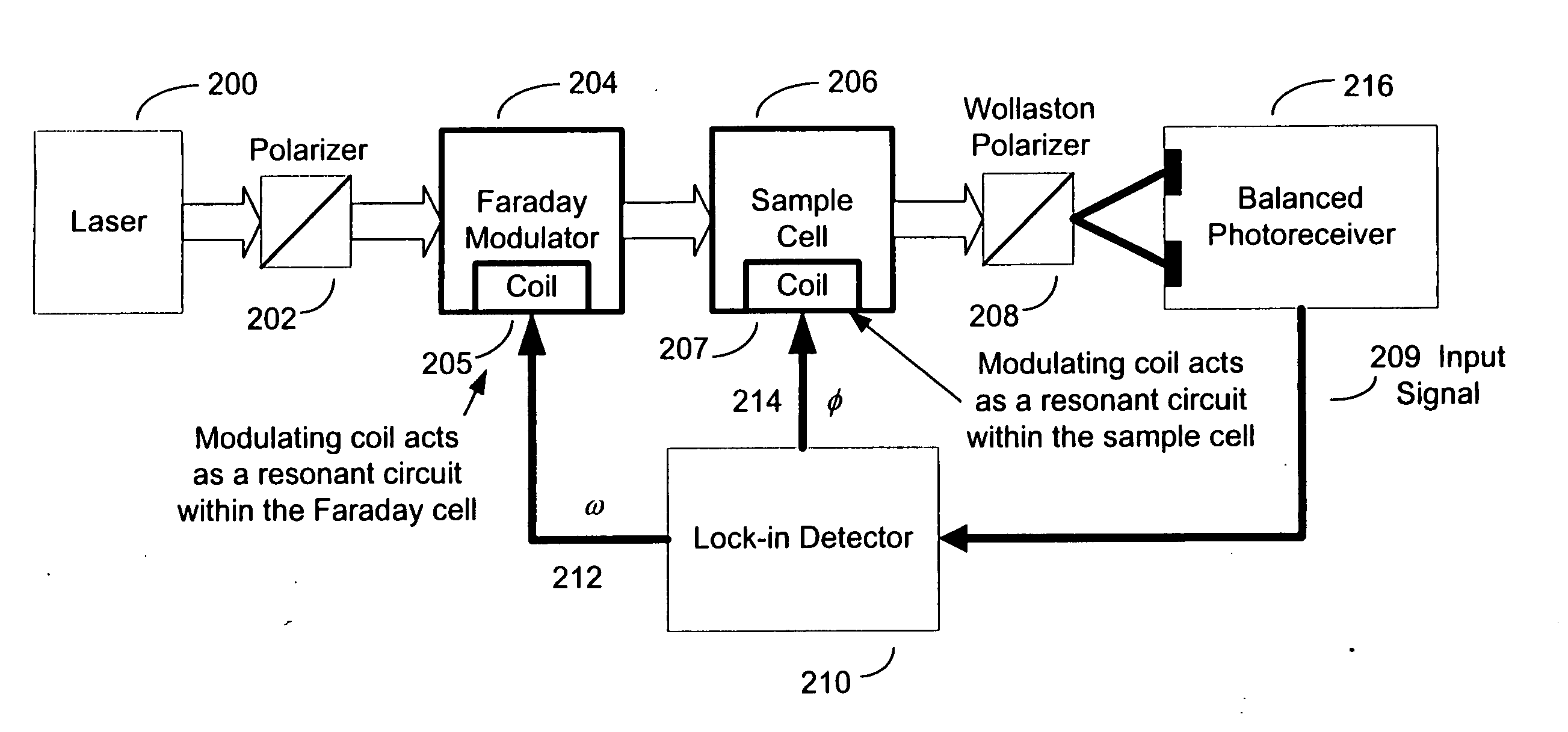
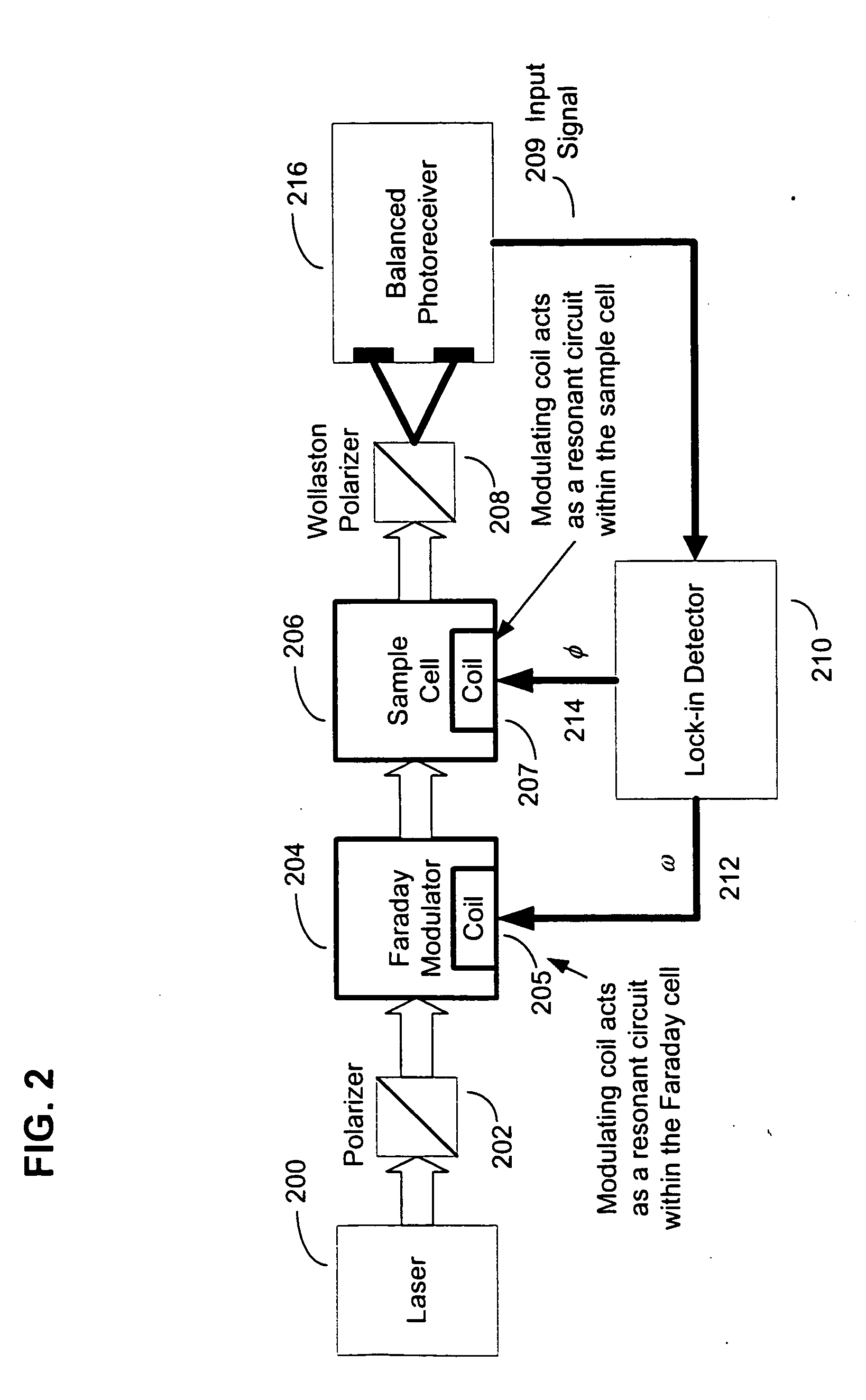
[0022]FIG. 2 illustrates an exemplary block diagram of an exemplary chiroptical heterodyning system, which is an exemplary operating environment for methods and systems that automatically tune a resonant circuit according to an embodiment of the present invention. Referring now to FIG. 2, a laser 200 generates a probe beam of light provided to a polarizer 202. Thereafter, the input linear polarization state of the probe beam may be adjusted or modulated with a Faraday modulator 204 in response to signal 212. If periodically modulated, the frequency of such modulation is designated ω. In an alternative embodiment, the Faraday modulator 204 may...


PUM

PropertyMeasurementUnit
frequencyaaaaaaaaaa
frequencyaaaaaaaaaa
frequencyaaaaaaaaaa

Abstract

An apparatus and method for automatically tuning a resonant circuit in a chiroptical measurement system. A sample cell holds a sample being measured for a chiroptical property as the sample is modulated by the resonant circuit. A signal source coupled to the resonant circuit generates a driving signal at one of a plurality of frequencies to modulate the resonant circuit. The frequencies are within a range of expected resonant frequencies for the resonant circuit. A feedback loop circuit coupled to the signal source is used to adjust the frequency of the driving signal to another of the frequencies in response to a feedback signal associated with a measured parameter of the driving signal. In this way, the frequency of the driving signal is adjusted to create a resonant condition. The driving signal may also be applied at a reduced power level so that the resonant circuit can be driven at off-resonant frequencies within the range of frequencies.

Description

RELATED APPLICATIONS [0001] The present application hereby claims the benefit of U.S. Provisional Patent Application Ser. No. 60 / 584,233, which was previously filed by the same inventors on Jun. 30, 2004.FIELD OF THE INVENTION [0002] This invention relates to systems for resonant circuit tuning and, more particularly, to systems and methods for automated resonant circuit tuning in a chiroptical measurement system. BACKGROUND OF THE INVENTION [0003] In general, a “chiral” object is one that is not superimposable upon its mirror image. In other words, a chiral object and its mirror image are similar in constitution or content, but different in orientation. Examples of chiral objects include a human hand, a mechanical screw, or a propeller. While the mirror images look similar, they have different characteristic orientations with regard to their parts (e.g., the digits on the hand, the helical orientation of the screw, and the pitch orientation of the blades on the propeller). [0004] I...

Claims


Application Information

Patent Timeline
Patent Type & Authority Applications(United States)
IPC IPC(8): H01P1/20G01N21/21H03J7/04H03J7/18H03L5/02
CPCG01N21/21H03J2200/08H03J7/18H03J7/04
Inventor GIBBS, PHILLIP R.
Owner GIBBS PHILLIP R
Why Eureka
Try Eureka