Apparatus for establishing signal coupling between a signal line and an antenna structure

a signal line and antenna technology, applied in the field of electromagnetic energy radiation and reception, can solve the problems of distorted radiated waveforms, unnecessary complications and expense to the overall system design, and many of the known uwb antennas do not meet this requiremen

Inactive Publication Date: 2003-01-28
HUMATICS CORP
View PDF20 Cites 163 Cited by
  • Summary
  • Abstract
  • Description
  • Claims
  • Application Information

AI Technical Summary

Benefits of technology

It is a further object of the present invention to provide a small omni-directional planar dipole antenna that can radiate energy efficiently with minimal reflection and distortion.

Problems solved by technology

Many of the known UWB antennas do not meet this requirement.
As a result, different frequency components are radiated from different parts of the antenna, and resulting radiated waveforms are distorted.
However, such corrective measures and structures add unnecessary complications and expense to overall system design.
Horn-type antennas can be non-dispersive, but they tend to be large, bulky and highly directive.
Small element antennas are known, such as bow-tie antennas, but they tend to have excessive reflections that can be offset only by resistive loading.
Resistive loading is a lossy solution that minimizes reflection at the cost of lowering radiation efficiency.
Non-resistive loaded small element antennas have been disclosed in U.S. Pat. No. 5,363,108 (issued Nov. 8, 1994) to Larry W. Fullerton. These antennas emit a short non-dispersive pulse, but tend to have significant reflections and less than desirable impedance matching.

Method used


Image

  • Apparatus for establishing signal coupling between a signal line and an antenna structure
  • Apparatus for establishing signal coupling between a signal line and an antenna structure
  • Apparatus for establishing signal coupling between a signal line and an antenna structure

Examples


Embodiment Construction

Overview of the Invention

The present invention will now be described more fully in detail with reference to the accompanying drawings, in which the preferred embodiments of the invention are shown. This invention should not, however, be construed as limited to the embodiments set forth herein; rather, they are provided so that this disclosure will be thorough and complete and will fully convey the scope of the invention to those skilled in art. Like numbers refer to like elements throughout.

Impulse Radio Basics

This section is directed to technology basics and provides the reader with an introduction to impulse radio concepts, as well as other relevant aspects of communications theory. This section includes subsections relating to waveforms, pulse trains, coding for energy smoothing and channelization, modulation, reception and demodulation, interference resistance, processing gain, capacity, multipath and propagation, distance measurement, and qualitative and quantitative characteri...


PUM


Abstract

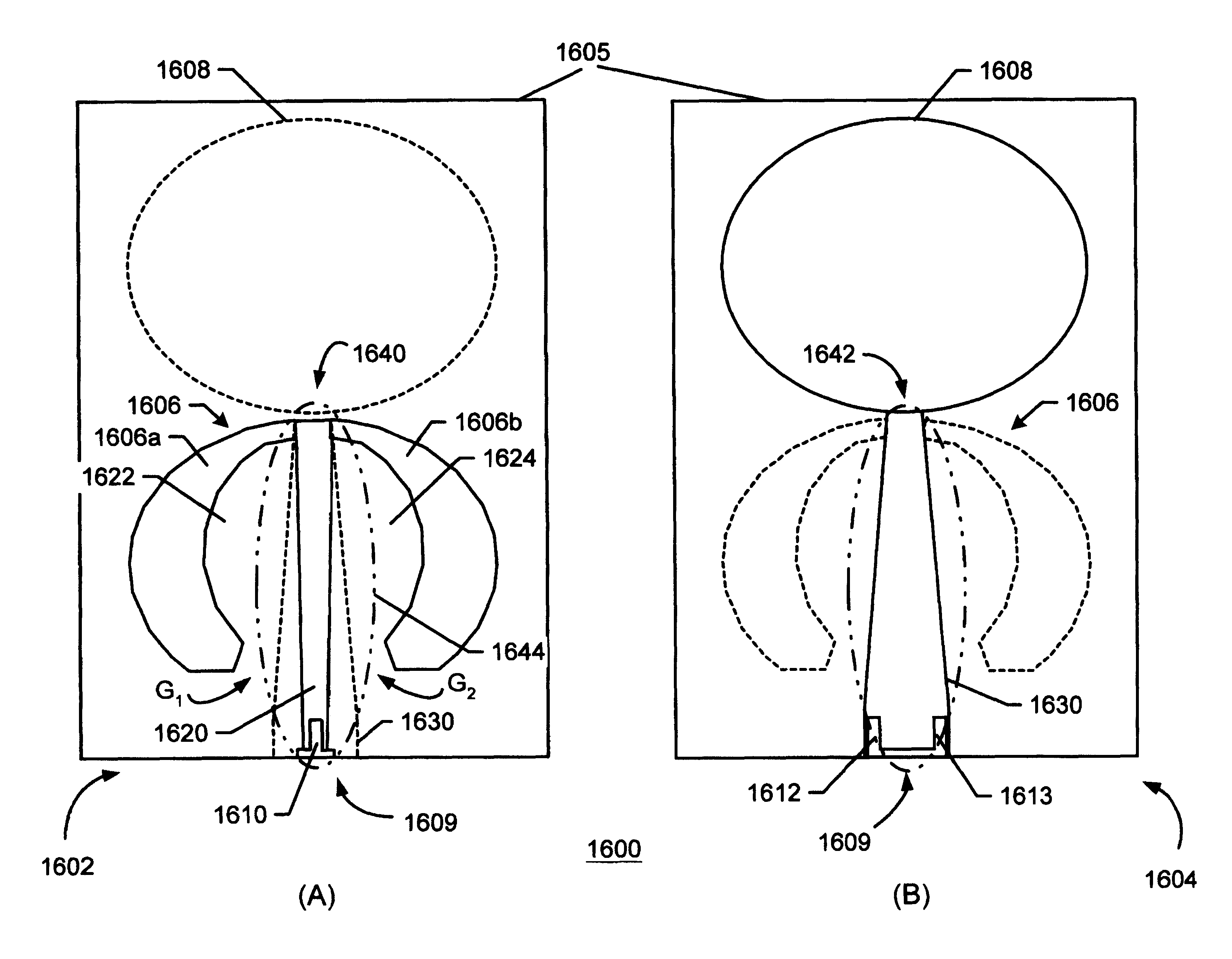
An apparatus for coupling a signal supply with an antenna including first and second elements. The signal supply delivers a signal to the antenna at a connection locus. The first element has a first edge and the second element has a second edge; the connection locus includes part of the first and second edges. The apparatus includes a first and second feed structure. The first feed structure extends a feed distance from the signal supply to the second edge and divides the first element into two lands in spaced relation with the first feed structure to establish a separation distance intermediate the first feed structure and the two lands. The second feed structure couples the signal supply with the first proximal edge. The separation distance establishes a signal transmission structure between the two lands and the first feed structure.

Description

1. Field of the InventionThe present invention relates generally to electromagnetic energy radiation and reception, and especially relates to electromagnetic energy radiation and reception effected using impulse radio energy. Still more particularly the present invention provides an antenna with an adjustable-impedance feed that is suited for broadband energy radiation and reception, and particularly well suited for broadband energy radiation and reception employing impulse radio energy.2. Related ArtRecent advances in communications technology have enabled an emerging, revolutionary ultra wideband technology (UWB) called impulse radio communications systems (hereinafter called impulse radio).Impulse radio was first fully described in a series of patents, including U.S. Pat. Nos. 4,641,317 (issued Feb. 3, 1987), 4,813,057 (issued Mar. 14, 1989), 4,979,186 (issued Dec. 18, 1990) and 5,363,108 (issued Nov. 8, 1994) to Larry W. Fullerton. A second generation of impulse radio patents in...

Claims


Application Information

Patent Timeline
Patent Type & Authority Patents(United States)
IPC IPC(8): H01Q13/10H01Q9/28H01Q9/40H01Q9/04H01Q9/00G10LH01Q13/00H01Q13/02H04B1/69
CPCH01Q9/005H01Q9/285H01Q13/10H01Q9/40H04B2001/6908
Inventor SCHANTZ, HANS GREGORY
Owner HUMATICS CORP
Why Eureka
Try Eureka