

Perpendicular magnetic recording apparatus having discrete track media
a magnetic recording and perpendicular technology, applied in the direction of magnetic recording heads, instruments, data recording, etc., can solve the problems of lowering the signal-to-noise ratio (snr) and no proposal to suppress the degradation of snr
- Summary
- Abstract
- Description
- Claims
- Application Information
AI Technical Summary
Benefits of technology
Problems solved by technology
Method used
Image

Examples
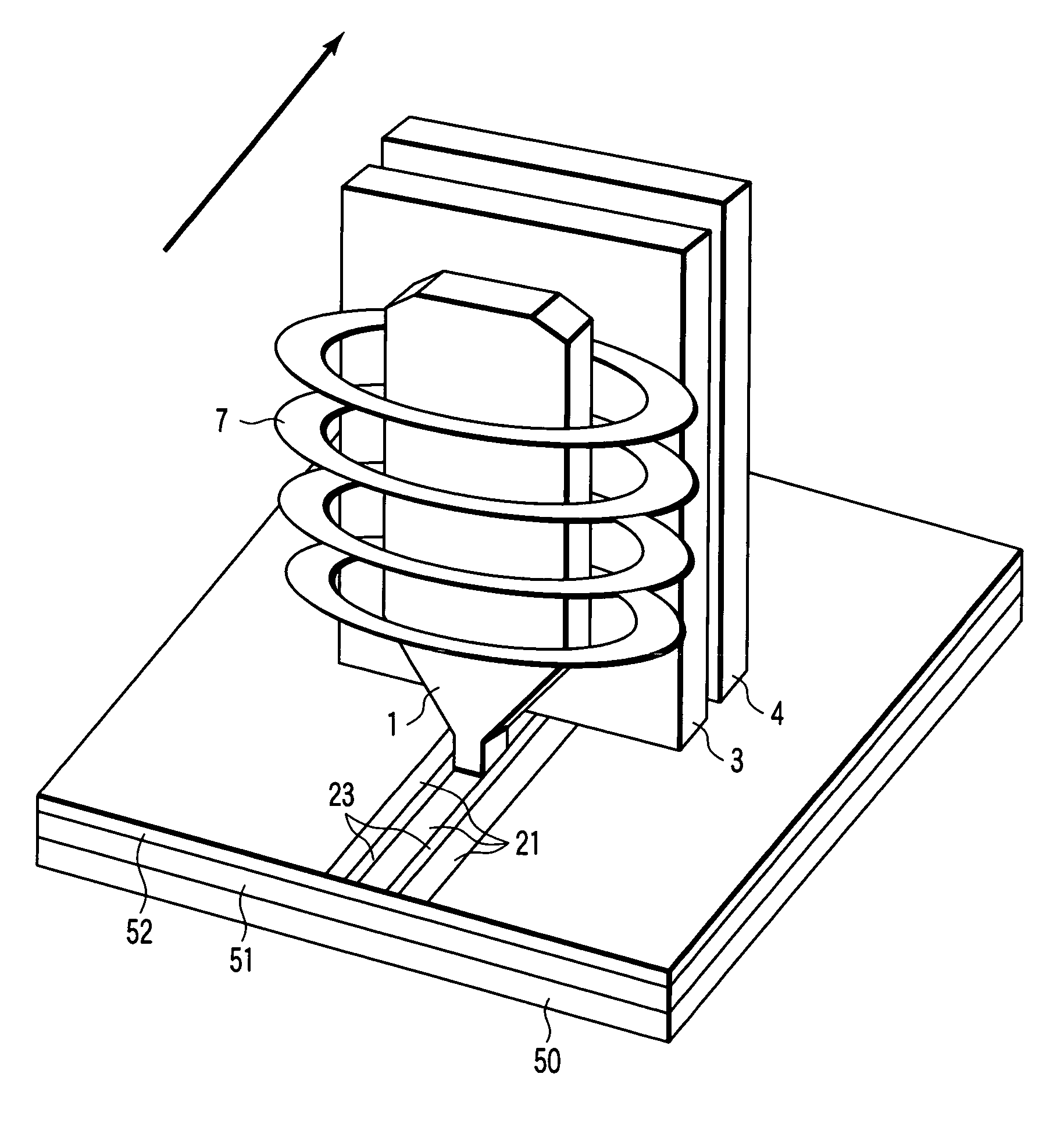
first embodiment
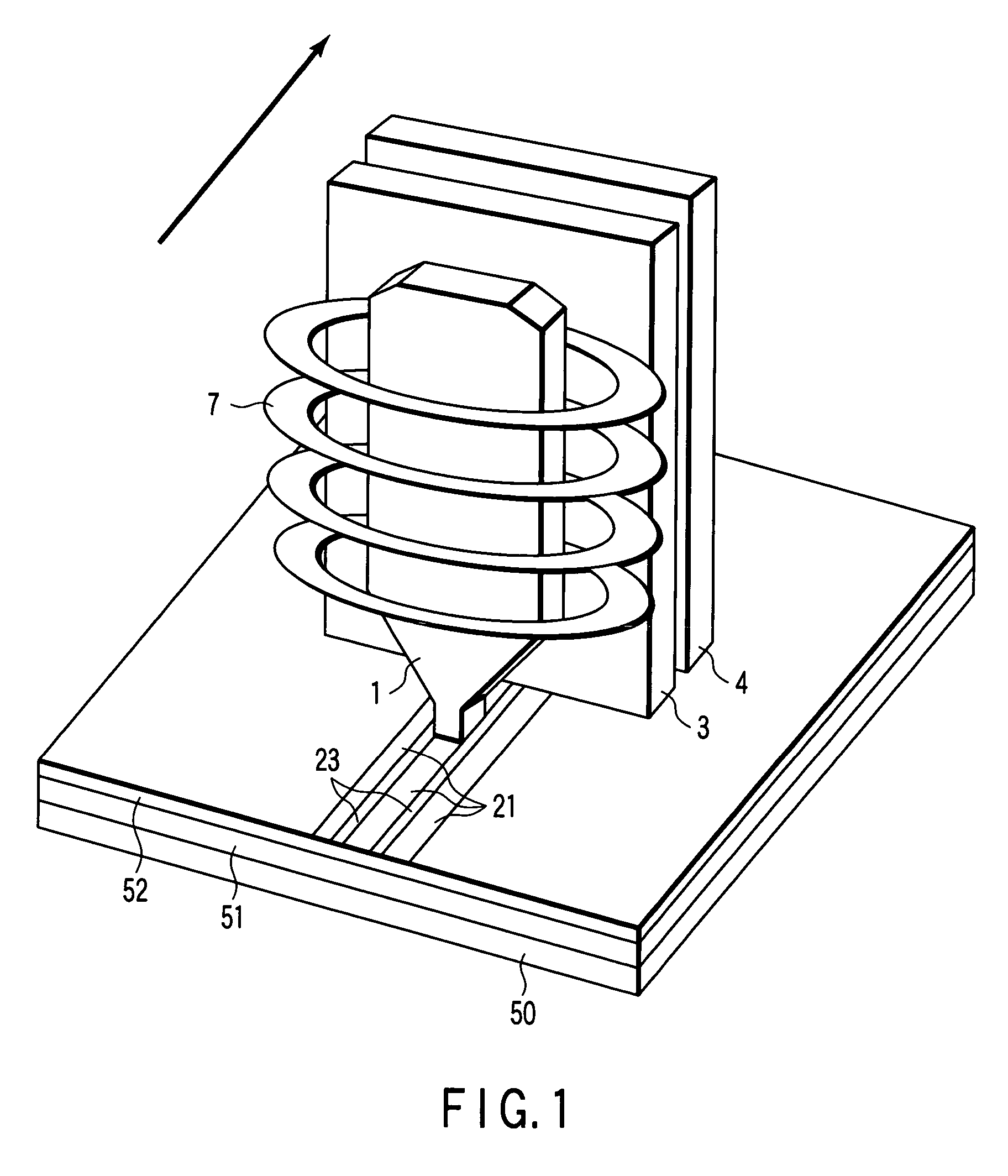
[0020]FIG. 2 is a plan view showing the shape of the main pole 1 on the air bearing surface (referred to as ABS hereinafter) positioned on the discrete track media incorporated in the perpendicular magnetic recording apparatus according to the present invention. As shown in FIG. 2, the width of each of the recording tracks 21 in the discrete track media is defined as a, and the width of each of the guard bands magnetically separating the adjacent recording tracks 21 is defined as b. FIG. 2 shows that the magnetic head or the main pole 1 is inclined at an angle θ (referred to as a skew angle hereinafter) from the head traveling direction. In FIG. 2, the main pole 1 has a shape on ABS of substantially rectangle. In connection with the shape on ABS of the main pole 1, the length of each side along the head traveling direction, i.e., the length between the trailing edge and the leading edge along the head traveling direction is defined as L, the track width at the trailing edge is defin...
second embodiment
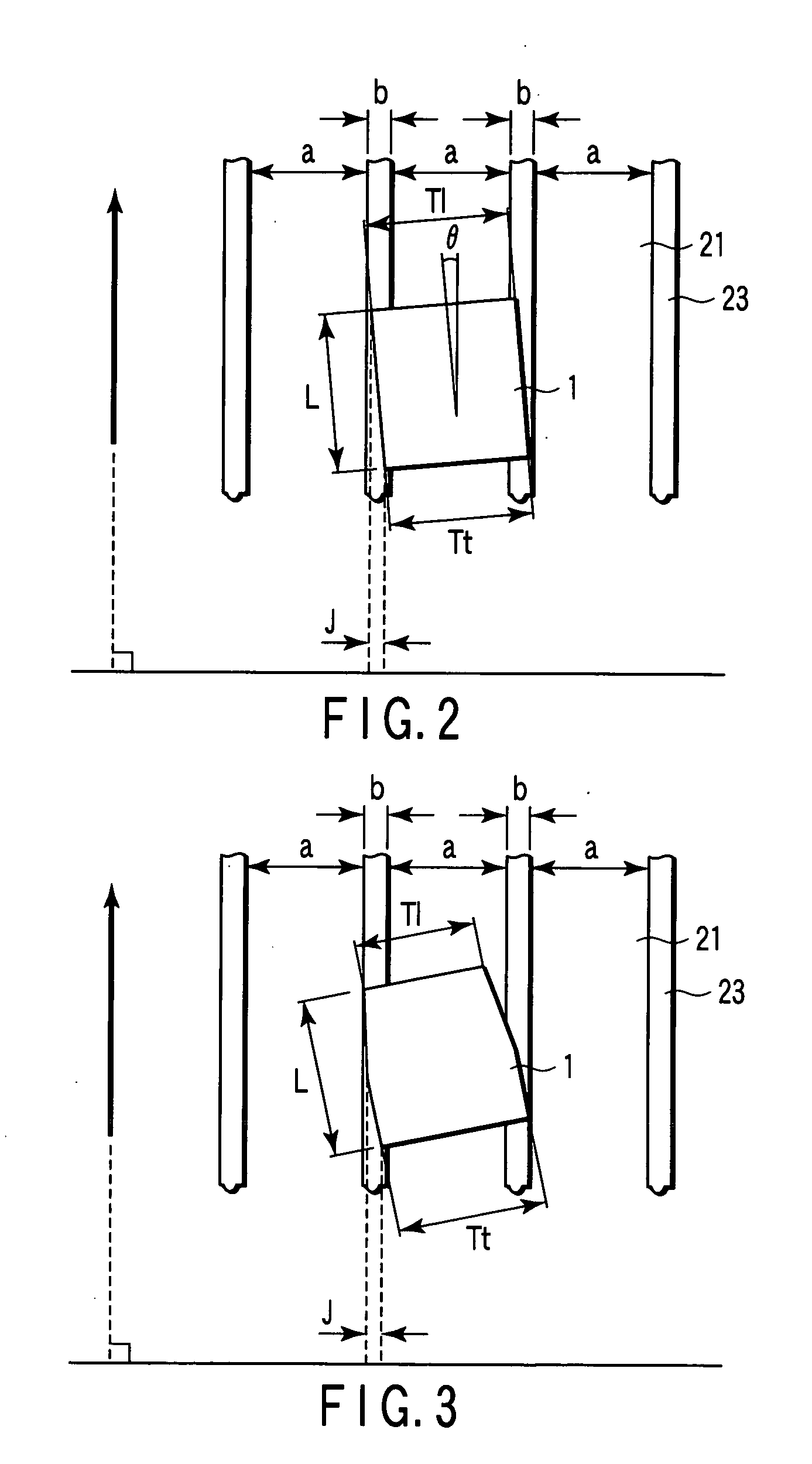
[0023]FIG. 3 is a plan view showing the shape of the main pole 1 on ABS positioned on the discrete track media incorporated in the perpendicular magnetic recording apparatus according to the present invention. The meanings of the symbols used for the discrete track media and main pole 1 are similar to those of the symbols in FIG. 2. FIG. 3 also shows that the main pole 1 is inclined at a certain skew angle to the head traveling direction. In FIG. 3, the main pole 1 has a shape on ABS of a hexagon with projections on both sides along the head traveling direction. As a result, the track width Tt at the trailing edge is larger than the track width Tl at the leading edge. The main pole 1 may have such a shape on ABS that a plurality of projections is provided on both sides along the head traveling direction.
[0024] Also in FIG. 3, the length J of a line segment which is formed by projecting a side of the main pole along the head traveling direction onto a straight line perpendicular to t...
third embodiment
[0025]FIG. 4 is a plan view showing the shape of the main pole 1 on ABS positioned on the discrete track media incorporated in the perpendicular magnetic recording apparatus according to the present invention. The meanings of the symbols used for the discrete track media and main pole 1 are similar to those of the symbols in FIG. 2. FIG. 4 also shows that the main pole 1 is inclined at a certain skew angle to the head traveling direction. In FIG. 4, the main pole 1 has a shape on ABS of an octagon with projections and recesses on both sides along the head traveling direction. As a result, the track width Tt at the trailing edge is larger than the track width Tl at the leading edge. The main pole 1 may have such a shape on ABS that a plurality of projections or recesses is provided on both sides along the head traveling direction.
[0026] Also in FIG. 4, the length J of a line segment which is formed by projecting a side of the main pole along the head traveling direction onto a straig...
PUM
| Property | Measurement | Unit |
|---|---|---|
| soft magnetic | aaaaa | aaaaa |
| length | aaaaa | aaaaa |
| width | aaaaa | aaaaa |
Abstract
Description
Claims
Application Information