Backlight unit of liquid crystal display

a liquid crystal display and backlight technology, applied in the field of direct type backlight units of lcds, can solve the problems of lcd tvs, lcd monitor and lcd tvs with direct backlight units that are more prone to failure than edge type backlight units, and achieve the effect of facilitating lamp installation

Inactive Publication Date: 2006-01-05
LG DISPLAY CO LTD
View PDF19 Cites 4 Cited by
  • Summary
  • Abstract
  • Description
  • Claims
  • Application Information

AI Technical Summary

Benefits of technology

[0031] The present invention provides a backlight unit having lamp support structures uniquely fitted for asymmetric lamp holder ends to facilitate installation of the lamp in a particular orientation. In addition, because the lamp surface of the present invention is treated to emit light at different intensities, light can be uniformly projected from the disclosed backlight unit to a panel, such as LCD panel, in which the backlight unit is used.

Problems solved by technology

However, CRTs are heavy and bulky and there is a growing demand for slim, light-weight electrical devices.
However, because direct type backlight units usually operate longer and utilize more lamps than edge type backlight units, direct type backlight units in large LCD monitors and LCD TVs are more prone to fail than edge type backlight units.
Direct type backlight units are more prone to problems because they include a plurality of lamps under a LCD panel.
Regardless, having to replace lamps in either case decreases luminescence efficiency.
However, if light intensity differs depending on the radial direction of the lamp surface, installation of arbitrarily oriented lamps may provide suboptimal performance, including non-uniform brightness and deteriorating image quality.
In the related art, it is not easy to install a surface treated lamp oriented in a proper direction.
To do so, would require a loss in productivity.
Moreover, even if the lamp were installed in a proper orientation, the vibration and impact associated with long-term use may alter the orientation.

Method used


Image

  • Backlight unit of liquid crystal display
  • Backlight unit of liquid crystal display
  • Backlight unit of liquid crystal display

Examples


Embodiment Construction

[0045] Reference to various embodiments of the present invention will now be made, examples of which are described in the specification and claims and illustrated in FIGS. 4-7.

[0046] The present invention relates to a direct type backlight unit and to an LCD device including a backlight unit of the present invention. LCD devices in accordance with the present invention may employ any of the inventive backlight unit embodiments disclosed in the specification and claims.

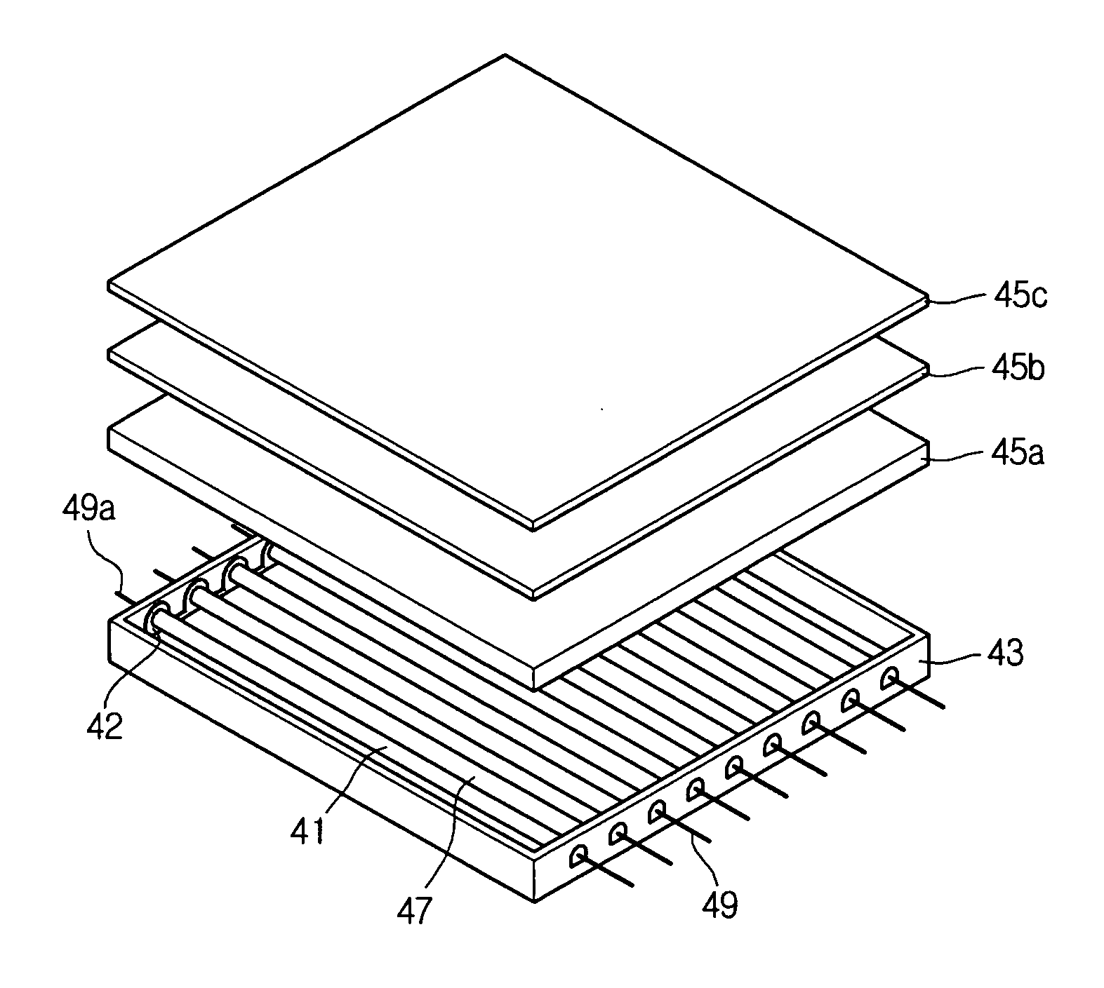
[0047] When compared with a backlight unit of the related art, a backlight unit of the present invention characteristically includes a plurality of lamps, lamp holders, and lamp supports, in which the lamp holders and lamp supports share asymmetric structures for fixing lamps to lamp supports in a specific orientation or direction. In a further aspect, the backlight units of the present invention may further include lamps emitting light with different intensities depending on the orientation or direction in which the...


PUM


Abstract

The present invention provides a backlight unit and an LCD device having the same, where the backlight unit contains lamp support structures uniquely fitted to facilitate installation of lamps in a particular orientation. The fixedly oriented lamps may be further treated to emit light with different intensities so that light can be more uniformly projected from the disclosed backlight unit to a panel, such as LCD panel, in an LCD device.

Description

[0001] This application claims the benefit of priority under 35 U.S.C. § 119 to Korean application 50546 / 2004, filed Jun. 30, 2004. BACKGROUND OF THE INVENTION [0002] 1. Field of the Invention [0003] The present invention relates to a liquid crystal display (LCD), and more particularly, to a direct type backlight unit of an LCD. [0004] 2. Description of the Related Art [0005] A cathode ray tube (CRT) is an electrical device for displaying images. CRTs are found in computer monitors, televisions, oscilloscopes, etc. However, CRTs are heavy and bulky and there is a growing demand for slim, light-weight electrical devices. [0006] Other types of display devices have been developed to replace the heavy and bulky CRTs, including LCDs utilizing optical property effects, plasma display panels (PDPs) utilizing plasma discharge effects, and electro luminescence displays (ELDs) utilizing electroluminescence effects. [0007] Recently, thin, light-weight, low power consuming LCDs have been develo...

Claims


Application Information

Patent Timeline
Patent Type & Authority Applications(United States)
IPC IPC(8): F21V7/04
CPCF21V19/008G02F1/133604H01J61/35G02F2201/503G02F1/133608G02F1/1335
Inventor MOON, JEONG MIN
Owner LG DISPLAY CO LTD
Why Eureka
Try Eureka