
Wireless device, method for wireless communication system, and wireless communication system

Inactive Publication Date: 2006-01-05
HITACHI INFORMATION & CONTROL SOLUTIONS LTD
View PDF6 Cites 48 Cited by
  • Summary
  • Abstract
  • Description
  • Claims
  • Application Information

AI Technical Summary

Benefits of technology

[0012] In view of the problems described above, the present invention provides a wireless device that allows the wireless devices to communicate each other via intermediary relay devices, that is used in a wireless network where intermediary relay devices are sometimes moved or the power is turned off, that minimizes the need to re-search for a communication route, and that provides a stable, reliable communication environment.
[0015] The present invention provides a wireless device, a wireless communication system control method, and a wireless communication system for providing a communication environment that minimizes the need for route re-search processing and ensures stable operation.

Problems solved by technology

On the other hand, connecting those electrical appliances to a network requires network construction work in the home and buildings, and the network construction work requires technical knowledge about the communication cable wiring and connections as well as hard work and high construction costs.
However, when an intermediary relay device moves from one place to another or the power is turned off after a communication route is determined, the communication route using the intermediary relay device cannot be used.
In general, this communication route search is complex and time-consuming.
Another problem is that, immediately after an intermediary relay device moves or the power is turned off, a data packet being transferred is stored in the buffer of the intermediary relay device until a new destination is found.
When the buffer of the intermediary relay device becomes full, a packet loss may occur.
Searching for a new communication route also requires the transmission of many data packets and, , therefore, more packets tend to be lost due to an increase in the traffic.
A packet loss also involves the frequent retransmission of a packet at an application level, meaning that more and more wasteful data packets are generated.

Method used


Image

  • Wireless device, method for wireless communication system, and wireless communication system
  • Wireless device, method for wireless communication system, and wireless communication system
  • Wireless device, method for wireless communication system, and wireless communication system

Examples


Embodiment Construction

Example of General Configuration

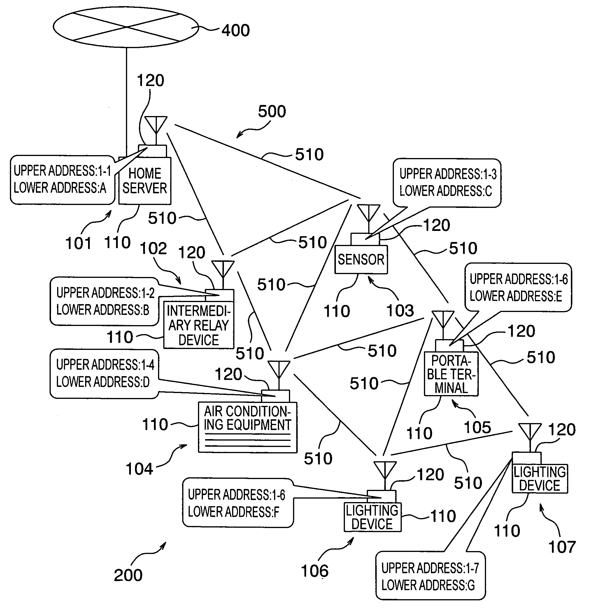
[0058]FIG. 1 shows the general configuration of a wireless communication system 200 including a wireless device 100 in this embodiment. This figure shows an example of the wireless communication system 200 configured by using various home electrical appliances and electrical appliances in the home as wireless devices 100. The wireless communication system 200 in this embodiment may be used in the home, in an office or a building, and even outdoors. As shown in FIG. 1, a home server 101, an specialized intermediary relay device 102, a sensor 103, air conditioning equipment 104, a portable terminal 105, a lighting device 106, and a lighting device 107 are used in this embodiment as wireless devices 100.

[0059] The home server 101 functions as a gateway that controls the communication between a network (second network) 500, to which the wireless devices 100 of the above-mentioned wireless communication system 200 in the home are connected, and a networ...


PUM


Abstract

A wireless device according to the present invention minimizes the need for changing a communication route in an ad hoc network including wireless devices used for base stations, fixed stations, and mobile stations that are turned on / off or moved, wherein, when wireless devices cannot directly send or receive radio waves, data can be transmitted between them by relaying data via other wireless devices that can directly send or receive radio waves (multi-hopping). In selecting a communication route, a communication route that includes wireless devices that are turned off or moved least frequently is selected.

Description

[0001] The present application claims priority from Japanese application JP 2004-198103 filed on Jul. 5, 2004, the content of which is hereby incorporated by reference into this application. BACKGROUND OF THE INVENTION [0002] The present invention relates to a wireless device, a control method for a wireless communication system, and a wireless communication system. [0003] A recent advance in the information communication technology has resulted in the development of many electrical appliances with the network communication function. Those electrical appliances, used in the home or offices, have computerized houses and buildings, leading to the development of a technology for providing more convenient, comfortable living environments. [0004] On the other hand, connecting those electrical appliances to a network requires network construction work in the home and buildings, and the network construction work requires technical knowledge about the communication cable wiring and connecti...

Claims


Application Information

Patent Timeline
IPC IPC(8): H04J3/24H04W16/26H04W40/14H04W74/08H04W84/12H04W84/18
CPCH04L12/2803H04L45/00H04L45/26H04W40/24H04L2012/2841H04W40/02H04L45/54H04W40/14H04L12/28H04W84/18
Inventor KAWAGUCHI, TAKAMASAANDO, NOBUYOSHIFUJIOKA, TAKAYOSHI
Owner HITACHI INFORMATION & CONTROL SOLUTIONS LTD
Features
  • Generate Ideas
  • Intellectual Property
  • Life Sciences
  • Materials
  • Tech Scout
  • Unparalleled Data Quality
  • Higher Quality Content
  • 60% Fewer Hallucinations
Learn More