Microphone device

a microphone and microphone technology, applied in the direction of electrical transducers, piezoelectric/electrostrictive transducers, transducer types, etc., can solve the problems of vibration noise and noise occurrence, and achieve the effect of positively preventing vibration noise caused by shaking and effective preventing the shaking of the microphone uni

Active Publication Date: 2006-01-05
AUDIO-TECHNICA
View PDF4 Cites 29 Cited by
  • Summary
  • Abstract
  • Description
  • Claims
  • Application Information

AI Technical Summary

Benefits of technology

[0009] With this configuration, the microphone unit is held by the plate-like elastic body to form the unit mounter, so that it is possible ...

Problems solved by technology

A diaphragm vibrates not only with sound waves but also with, for example, vibrations propagated through a microphone case, resulting in the occurrence of noise.
Most of the noise is handling noise generated by rubbing a microphone case ...

Method used


Image

  • Microphone device
  • Microphone device
  • Microphone device

Examples


Embodiment Construction

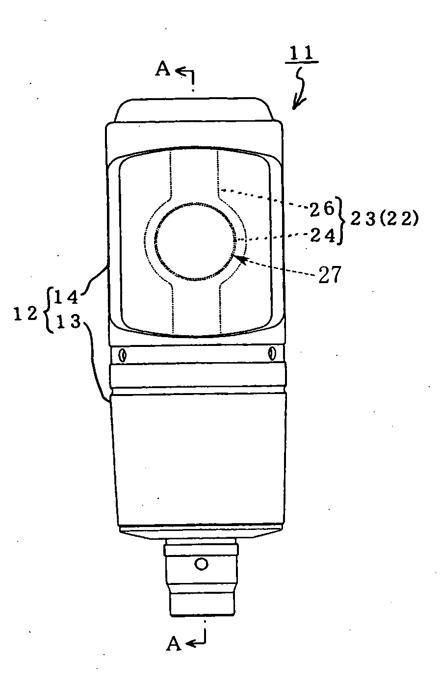
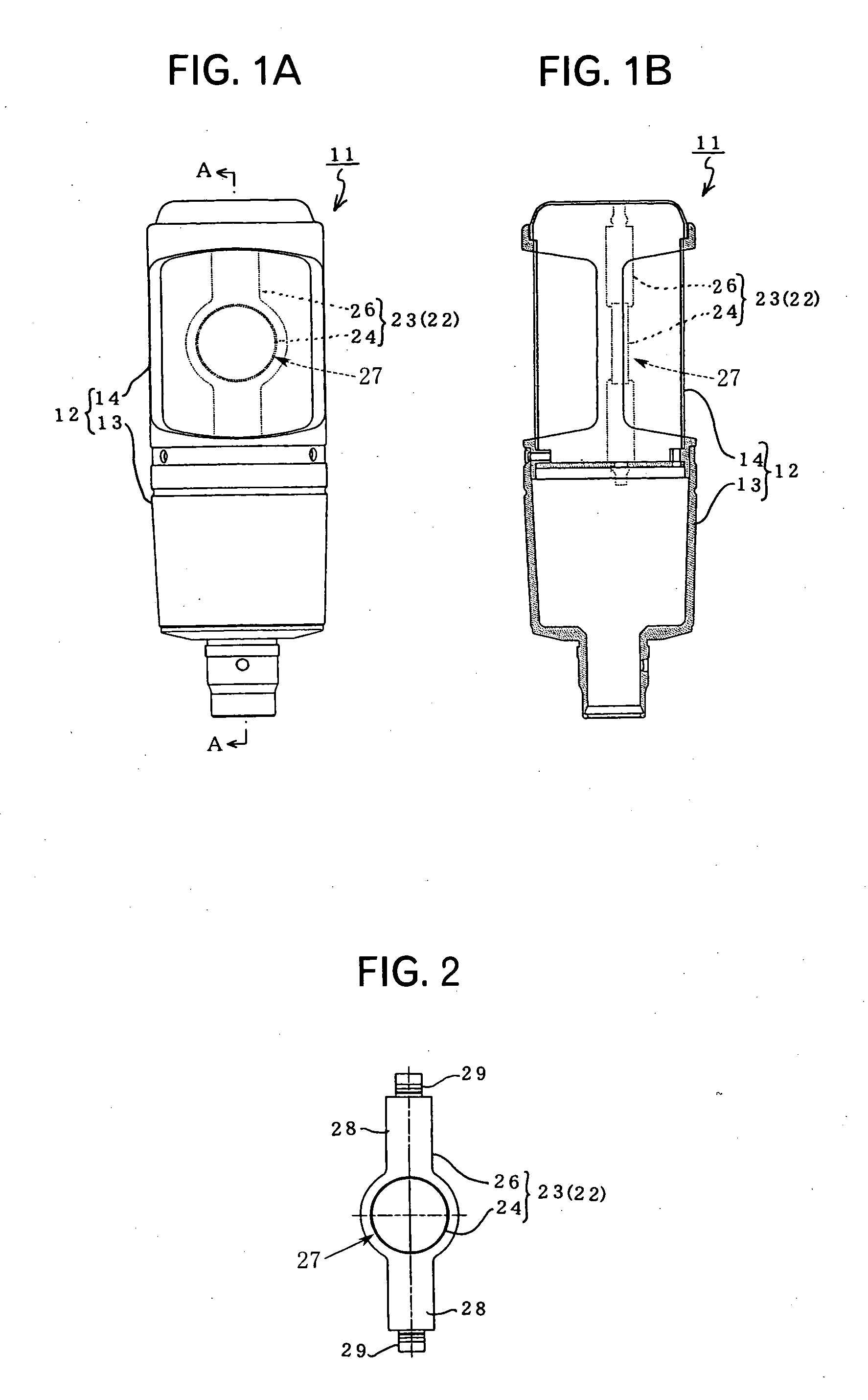
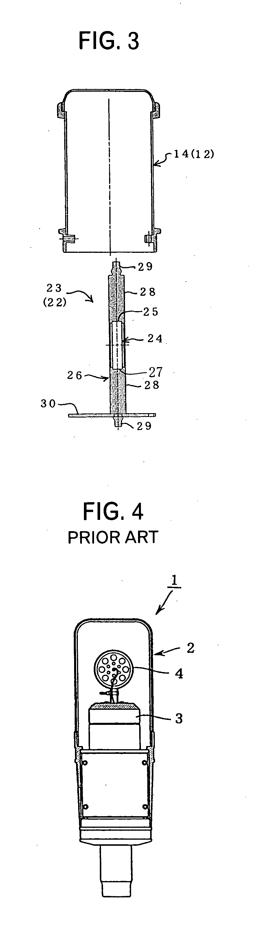
[0015]FIG. 1A is a front view showing a microphone device according to an embodiment of the present invention. FIG. 1B is a diagram taken along line A-A, in which the internal structure is partially omitted. FIG. 2 is a front view showing a unit mounter of FIG. 1. FIG. 3 is an exploded sectional view showing the arrangement of the unit mounter and a microphone case.

[0016] In this configuration, a microphone device 11 supported on a stand (not shown) comprises a microphone case 12 and a microphone body 22 housed in the microphone case 12.

[0017] The microphone case 12 is divided into two of a lower case 13 connected to the stand and an upper case 14 surrounded by a punching metal. The lower case 13 houses an electric circuit board (not shown) including, for example, a signal amplifier circuit and an impedance converter composed of an FET which are constituent elements of the microphone body 22.

[0018] As shown in FIG. 2, the upper case 14 houses a unit mounter 23 which is a constitu...


PUM


Abstract

There is provided a microphone device which can positively prevent vibration noise caused by a microphone unit shaking its head back and forth. A microphone unit 24 is held by a unit mounter 23 composed of a plate-like elastic body 26, and the two upper and lower points of the unit mounter 23 are respectively fixed to upper and lower points of the microphone case, thereby preventing the microphone unit 24 from shaking its head.

Description

TECHNICAL FIELD [0001] The present invention relates to a microphone device and more specifically relates to a technique for a microphone device in which a microphone unit is supported in a microphone case so as not to shake back and forth, thereby preventing the occurrence of vibration noise. BACKGROUND ART [0002] Microphone devices include a condenser microphone and a dynamic microphone which inevitably have diaphragms vibrating with sound waves. A diaphragm vibrates not only with sound waves but also with, for example, vibrations propagated through a microphone case, resulting in the occurrence of noise. Most of the noise is handling noise generated by rubbing a microphone case with hands. [0003]FIG. 4 is a front sectional view showing an example of a conventional stand microphone. In this example, a microphone 1 has a base 3 mounted in a microphone case 2. A microphone unit 4 is fixed on the base 3 via the lower end of the microphone unit 4. For example, Japanese Patent Applicat...

Claims


Application Information

Patent Timeline
IPC IPC(8): H04R11/04
CPCH04R1/021
Inventor AKINO, HIROSHI
Owner AUDIO-TECHNICA
Why Eureka
Try Eureka