Charge-metered biomedical stimulator

Inactive Publication Date: 2006-01-05
UNIV OF SOUTHERN CALIFORNIA
View PDF13 Cites 60 Cited by
  • Summary
  • Abstract
  • Description
  • Claims
  • Application Information

AI Technical Summary

Benefits of technology

[0011] The exemplary embodiments of the charge meter circuits, systems and methods described herein can be used to control power and stimulation in biomedical stimulators. They can avoid all of the above shortcomings by directly controlling the single stimulus parameter that determines both t

Problems solved by technology

Various existing biomedical stimulators often have circuits that require substantial space for current regulating transistors.
Such circuits tend to go out of current regulation if the product of the requested current and the impedance of the rest of the circuit, including electrodes, leads and perhaps coupling capacitors, exceeds the available compliance voltage.
This problem can be particularly severe for stimulators powered by inductive coupling, whose operating voltages tend to fluctuate with the strength of that coupling.
In applications requiring large numbers of densely packed stimulation channels, such heating can damage surrounding tissues.
Typical circuits in voltage-regulated biomedical stimulators also drop most of the supply voltage across the output transistors so as to accommodate a wide range of possible output v

Method used


Image

  • Charge-metered biomedical stimulator
  • Charge-metered biomedical stimulator
  • Charge-metered biomedical stimulator

Examples


Embodiment Construction

[0026] The detailed description set forth below in connection with the appended drawings is intended as a description of exemplary embodiments and is not intended to represent the only embodiments in which the biomedical stimulation devices, methods and systems can be practiced. The term “exemplary” used throughout this description means “serving as an example, instance, or illustration,” and should not necessarily be construed as preferred or advantageous over other embodiments. The detailed description includes specific details for the purpose of providing a thorough understanding of the biomedical stimulation devices, methods and systems. However, it will be apparent to those skilled in the art that the biomedical stimulation devices, methods and systems may be practiced without these specific details.

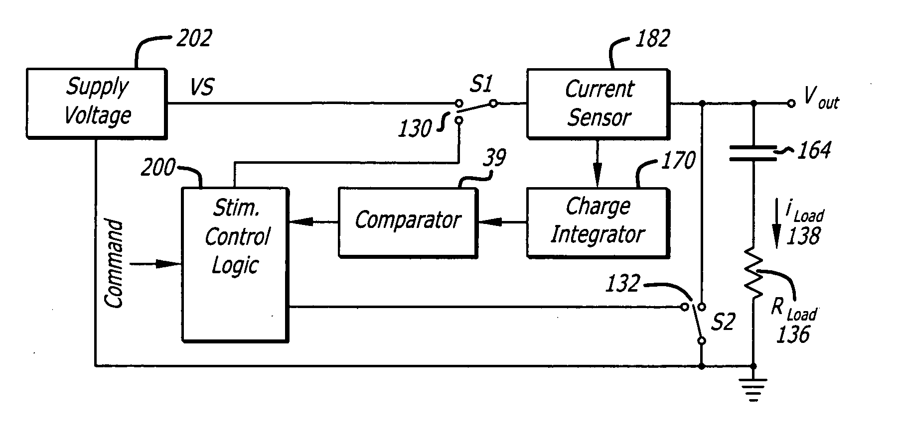
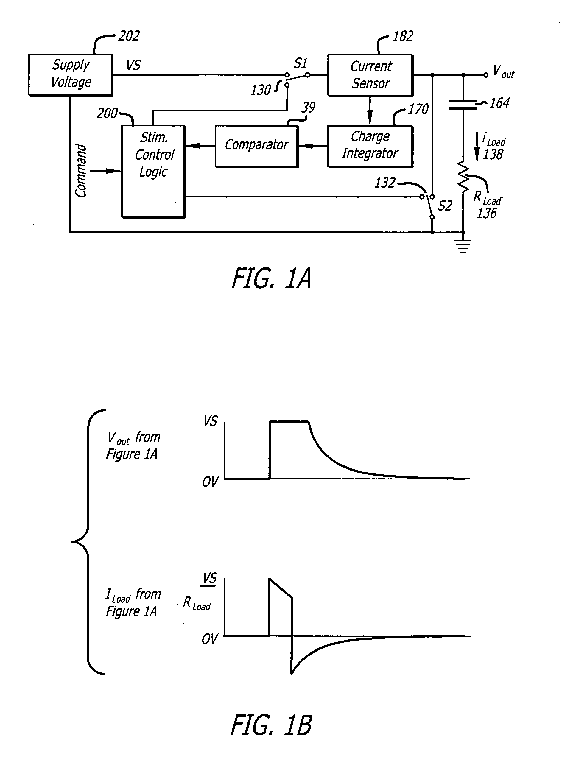
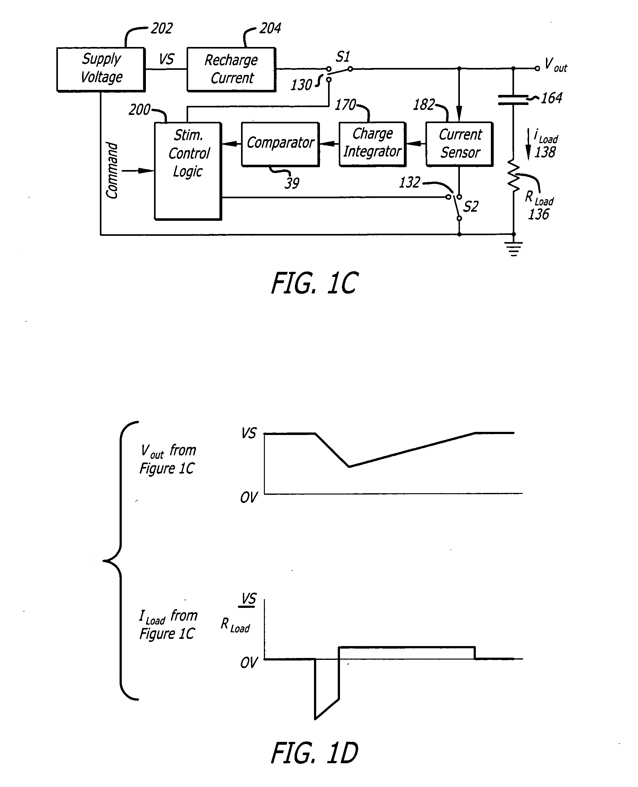
[0027] Effective stimulus of nerve tissue can benefit from monitoring and controlling the amount of charge delivered, rather than monitoring and controlling pulse duration or curre...


PUM


Abstract

Disclosed are biomedical stimulators and systems that deliver stimulus power efficiently to electrodes and tissues, provide reliable control of stimulus efficacy over a wide dynamic range of available power and voltage, avoid damaging net direct current flow through tissue, minimize the amount of data that must be transmitted to specify a particular stimulus strength, and extend the range of received field strengths for which stimulators can function safely and reliably. These biomedical stimulators and systems provide reliable stimulation of known intensity by measuring charging currents and discharging predetermined quantities of charge.

Description

CROSS-REFERENCE TO RELATED APPLICATIONS [0001] This application claims priority to U.S. Provisional Patent Application Ser. No. 60 / 577,440 filed Jun. 4, 2004, entitled “Charge-Metered Biomedical Stimulator,” the entire contents of which are incorporated herein by reference.STATEMENT OF GOVERNMENT RIGHTS [0002] The present invention has been made under a grant of NSF, federal grant no. EEC-0310723. Accordingly, the government may have certain rights to the present invention.BACKGROUND [0003] 1. Field [0004] This application relates generally to devices and methods for electrical stimulation of biological tissues. [0005] 2. General Background and State of the Art [0006] Power management can be important in the successful operation of electronics implanted in humans. In order to ensure the safety and effectiveness of biomedical stimulators, biomedical stimulators are typically designed to produce output pulses that are regulated on the basis of their pulse duration and either their vol...

Claims


Application Information

Patent Timeline
IPC IPC(8): A61N1/18A61N1/08A61N1/36A61N1/39
CPCA61N1/08A61N1/378A61N1/37205A61N1/3605
Inventor LOEB, GERALD E.WILLS, JACK D.
Owner UNIV OF SOUTHERN CALIFORNIA
Why Eureka
Try Eureka