Shoelace tightening structure

a shoelace and tightening technology, applied in the direction of shoelace fastening, footwear, fastening, etc., can solve the problems of inability to ensure the tightening of the shoelace with a constant tension, difficulty in tying or untying the action of the shoelace, and many drawbacks of the shoelace type shoes, so as to facilitate the wearer to tie the shoela

Inactive Publication Date: 2006-01-12
MIN DUCK GI
View PDF9 Cites 30 Cited by
  • Summary
  • Abstract
  • Description
  • Claims
  • Application Information

AI Technical Summary

Benefits of technology

[0004] Therefore, the present invention has been made in view of the above problems, and it is an object of the present invention to provide a shoelace tightening structure for making it easier for the wearer to tie shoelaces of shoelace-type shoes, including sports shoes.

Problems solved by technology

Such shoelace-type shoes, however, have several drawbacks due to the fact that the wearer has to tie or untie the shoelace whenever putting on or taking off the shoe.
That is, it is actually impossible to assure the shoelace to be tightened with a constant tension, and the tying or untying action of the shoelace may be difficult for some wearers, and requires a relatively long time.
Further, hanging ends of the shoelace, which remain after tying, may result in a low wearing comfort upon fluttering.

Method used


Image

  • Shoelace tightening structure
  • Shoelace tightening structure
  • Shoelace tightening structure

Examples


Embodiment Construction

[0010] Now, preferred embodiments of the present invention will be explained in detail with reference to the accompanying drawings.

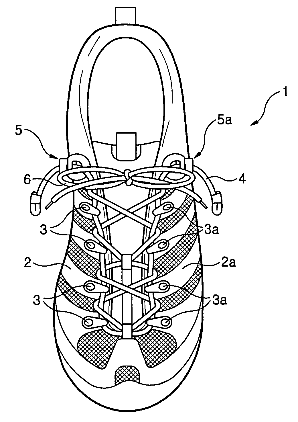
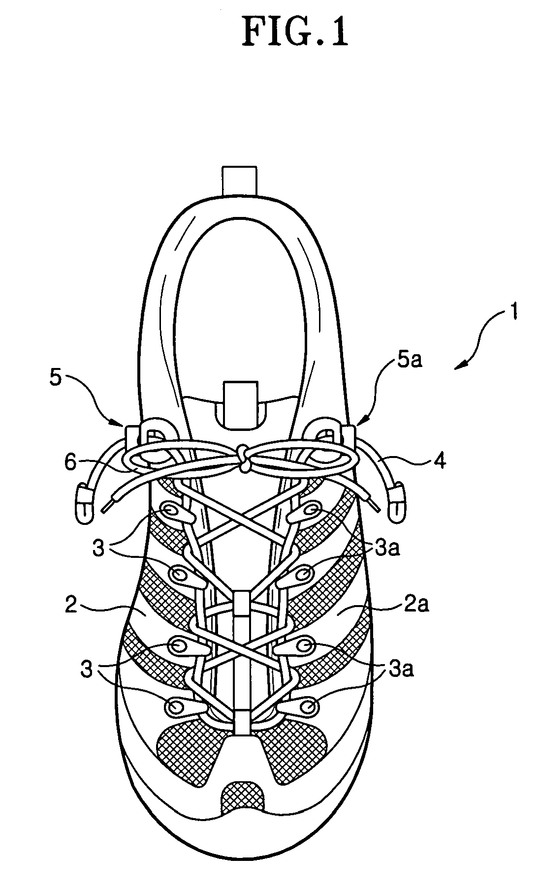
[0011] Referring to FIG. 1, a shoe 1, adopted in the present invention, is designed in such a fashion that two eyelet lines 2 and 2a are defined at left and right vamps, respectively, and a plurality of first and second row loops 3 and 3a are arranged along the eyelet lines 2 and 2a so that a tightening lace 4 is threaded therethrough. Here, the first row loops 3 and the second row loops 3 are symmetrically arranged in parallel to each other. At a portion, where lower ends of the eyelet lines 2 and 2a meet, is formed a center loop (not-designated) for use in the introduction of the tightening lace 4. With such a configuration, the tightening lace 4 is first threaded through the center loop so that it is centered thereon. On the basis of a center thereof, one-side portion of the tightening lace 4 is successively threaded upward through a plurality of the...


PUM


Abstract

Disclosed herein is a shoelace tightening device for making it easier for the wearer to tie shoelaces of shoelace-type shoes, including sports shoes. The shoelace tightening structure comprises a tightening lace, a pair of locking devices, and a shoelace. The tightening lace is successively threaded upward at both ends thereof through first and second row loops arranged in parallel along eyelet lines defined at left and right vamps of a shoe. The locking devices are fixed at opposite side positions above the eyelet lines. Through the locking devices are inserted both the ends of the tightening lace, respectively. The shoelace is tied on the tightening lace as both ends thereof alternately pass through portions of the tightening lace between the respective first row loops, and portions of the tightening lace between the respective second row loops so as to crisscross each other. The shoelace tightening structure of the present invention enables the wearer can easily tighten the shoe to conform closely with the shape of his/her foot by simply pulling the tightening lace, as well as can easily take off the shoe by pushing release buttons of the locking devices to loosen the tightening lace.

Description

TECHNICAL FIELD [0001] The present invention relates to a shoelace tightening structure for making it easier for the wearer to tie shoelaces of shoelace-type shoes, including sports shoes. BACKGROUND ART [0002] Generally, most widely used sports shoes are designed to enable the wearer to tighten his / her shoe to conform closely with the shape of the wearer's foot by using a shoelace, except for some shoes using velcro-fasteners. [0003] Such shoelace-type shoes, however, have several drawbacks due to the fact that the wearer has to tie or untie the shoelace whenever putting on or taking off the shoe. That is, it is actually impossible to assure the shoelace to be tightened with a constant tension, and the tying or untying action of the shoelace may be difficult for some wearers, and requires a relatively long time. Further, hanging ends of the shoelace, which remain after tying, may result in a low wearing comfort upon fluttering. DISCLOSURE OF THE INVENTION [0004] Therefore, the pres...

Claims


Application Information

Patent Timeline
Patent Type & Authority Applications(United States)
IPC IPC(8): A43C11/00
CPCA43C1/003Y10T24/37A43C9/04A43C7/00A43C11/22
Inventor MIN, DUCK GI
Owner MIN DUCK GI
Why Eureka
Try Eureka