Large-area slope concrete hidden-rail slip form structure and construction method

A concrete, large-area technology, applied in infrastructure engineering, water conservancy engineering, marine engineering and other directions, can solve the problems of difficult to maintain level, self-heavy, weak stability of the drawing system, etc., to improve the pouring quality, high installation accuracy, good stability

Inactive Publication Date: 2018-07-27
HANGZHOU JIANGRUN TECH LIMITED
View PDF0 Cites 9 Cited by
  • Summary
  • Abstract
  • Description
  • Claims
  • Application Information

AI Technical Summary

Problems solved by technology

[0003] The traditional trackless sliding form generally uses wooden formwork tracks on both sides or poured concrete to support, guide and control the pouring thickness of the concrete panel. It is difficult to ensure the stability and construction safety of the entire sliding formwork system during actual construction operations. In addition, it is difficult to properly solve a series of problems such as the buoyancy of concrete, the separation of aggregates during the process of concrete siloing, and the minimization of cracks in the panel, and it is also difficult to ensure that the slope concrete is poured in one time. The concrete pouring operation is obviously not enough to rely on the wooden formwork rails on both sides or the poured concrete to support it. The lower panel of the drag form is difficult to keep flat due to factors such as wide span and self-weight, and the stability of the entire draw form system during the construction process is also relatively low. weak
Concealed rail sliding form technology exists in the existing water conservancy engineering methods, but the stability of the concealed rail system is insufficient, and it increases the difficulty of surface steel reinforcement construction. Therefore, further research and innovation are still needed for concrete slipform construction on large-area slopes.

Method used


Image

  • Large-area slope concrete hidden-rail slip form structure and construction method
  • Large-area slope concrete hidden-rail slip form structure and construction method
  • Large-area slope concrete hidden-rail slip form structure and construction method

Examples


Embodiment Construction

[0033] In this embodiment, the production and processing process requirements of the drag form system, the construction technical requirements of concrete pouring, the construction technical requirements of steel bar binding, etc. will not be described in detail, and the implementation mode of the construction of the large-area slope concrete concealed rail sliding form involved in the present invention will be focused on .

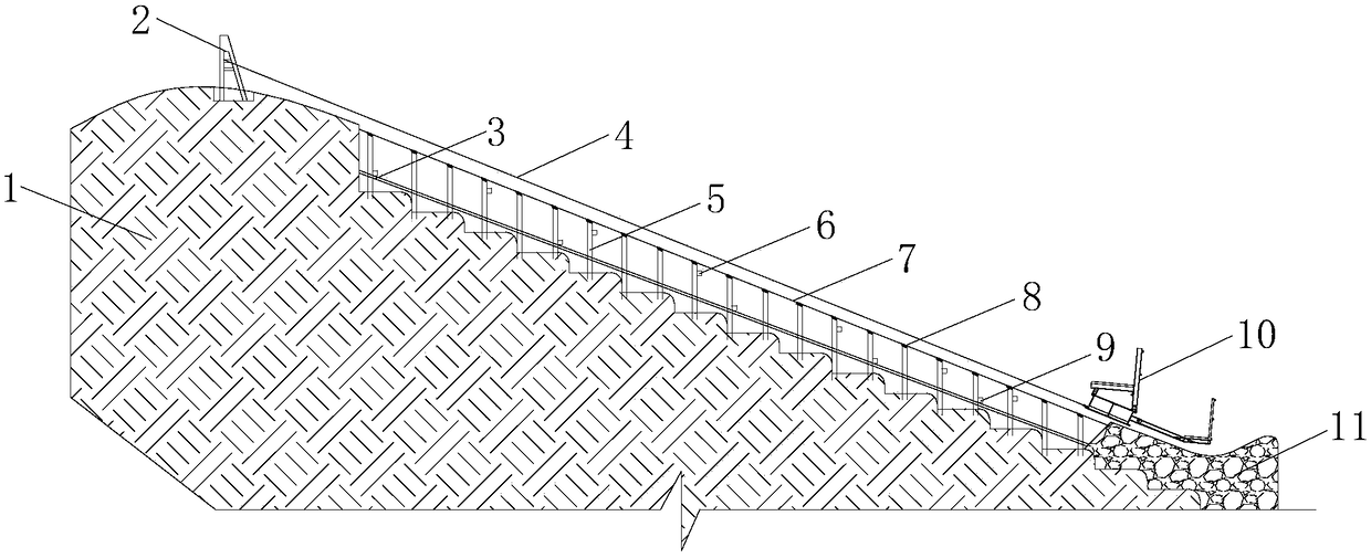
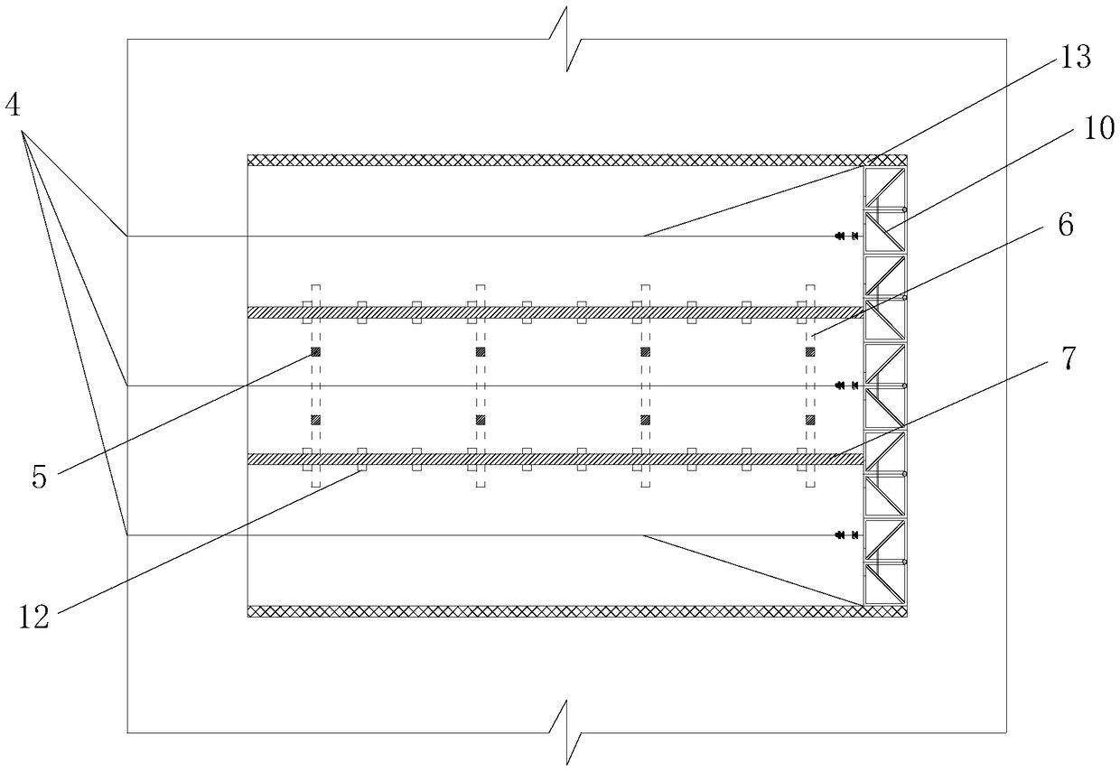
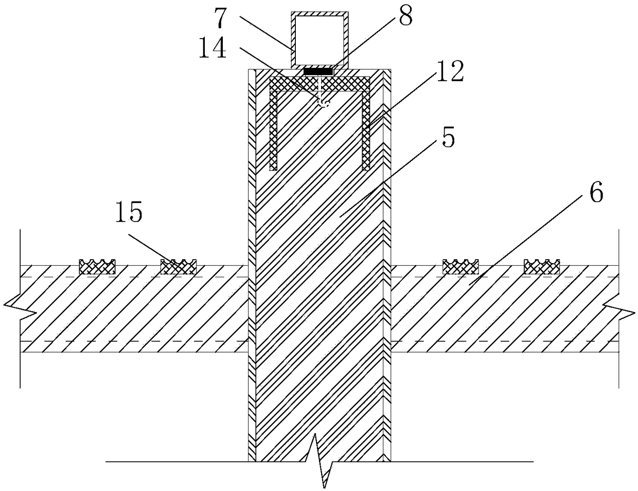
[0034] figure 1 It is a structural schematic diagram of the large-area slope concrete concealed rail sliding form of the present invention, figure 2 It is a schematic diagram of the concealed track layout of the present invention, image 3 It is a schematic diagram of the concealed track structure in the present invention, Figure 4 It is a schematic diagram of the side mold structure in the present invention, Figure 5 It is a schematic diagram of the mold dragging structure in the present invention, Figure 6 It is a construction process flow chart...


PUM


Abstract

The invention relates to a large-area slope concrete hidden-rail slip form structure. The structure comprises a slope top support pillar, vertical support columns, top connecting cross beams, bottom connecting cross beams, slip rails, combined side forms and pull forms. The vertical support columns are longitudinally and transversely arranged on an original slope at equal intervals, the top connecting cross beams and the bottom connecting cross beams are arranged at upper and lower ends of the vertical support columns respectively, and rebar positioning tooth plates are arranged on top surfaces of connecting beams; bracket plates are symmetrically arranged at the top of the rail support columns in the slope direction, rail pads are arranged on the bracket plates, and the slip rails are erected on the bracket plates; the combined side forms are mounted on two sides of the slope, and slip rails are also arranged in the combined side forms. The structure has the benefits as follows: an inner form body of a slip form system is divided into cavities uniformly at equal intervals, adjustable sand partition boards are arranged in the cavities to form limiting counterweight frames, and bagsbetween partition boards are filled with sand to realize area ballasting; flat plate vibrating tampers and vibrating leveling beams are arranged on lower panels of the slip forms, and the slope concrete pouring quality is further improved.

Description

technical field [0001] The invention relates to a slope concrete sliding form structure, in particular to a large-area slope concrete concealed rail sliding form structure and a construction method. Background technique [0002] At present, the continuous pouring of concrete on long slopes often adopts slipform construction. Since the actual construction process of traditional track-type slipform is relatively cumbersome, and additional sliding tracks are required, trackless slipform is often used. [0003] The traditional trackless sliding form generally uses wooden formwork tracks on both sides or poured concrete to support, guide and control the pouring thickness of the concrete panel. It is difficult to ensure the stability and construction safety of the entire sliding formwork system during actual construction operations. In addition, it is difficult to properly solve a series of problems such as the buoyancy of concrete, the separation of aggregates during the process ...

Claims


Application Information

Patent Timeline
Patent Type & Authority Applications(China)
IPC IPC(8): E02D15/02E02B7/20
CPCE02B7/20E02D15/02
Inventor 王新泉
Owner HANGZHOU JIANGRUN TECH LIMITED
Why Eureka
Try Eureka