Eureka AIR delivers breakthrough ideas for toughest innovation challenges, trusted by R&D personnel around the world.

Suture material for pneumatic suture instrument

a suture material and suture technology, applied in the field of suture instruments, can solve the problems of additional tissue insult and the need to reinsert, and achieve the effect of facilitating the separation of the delivered strand and entrainment of the sutur

Inactive Publication Date: 2007-09-13
FARRIS ALEX F
View PDF10 Cites 11 Cited by
  • Summary
  • Abstract
  • Description
  • Claims
  • Application Information

AI Technical Summary

Benefits of technology

[0008] Individual suture strands are provided at a predetermined length corresponding to a required penetration depth to stitch the site of interest and should also allow the free ends of the strand to remain external the body for the surgeon to easily tie and manipulate the knot to a point adjacent the tissues to be joined.
[0009] A continuous strand of suture material has a plurality of surface irregularities spaced apart along its length. Each surface irregularity is spaced at a predetermined distance corresponding to a required penetration depth to stitch the site of interest and also allow the free ends of the strand to remain external the body for the surgeon to tie and manipulate the knot. A notch in the suture material adjacent a subsequent abrasion or protrusion is provided to facilitate separation of a delivered strand of suture material from the remaining strand of suture material.

Problems solved by technology

In addition, should the free end of the suture be inadvertently pulled free of the tissue penetration points, additional tissue insult may be necessary to reinsert the suture material through the tissues.

Method used


Image

  • Suture material for pneumatic suture instrument
  • Suture material for pneumatic suture instrument
  • Suture material for pneumatic suture instrument

Examples


Embodiment Construction

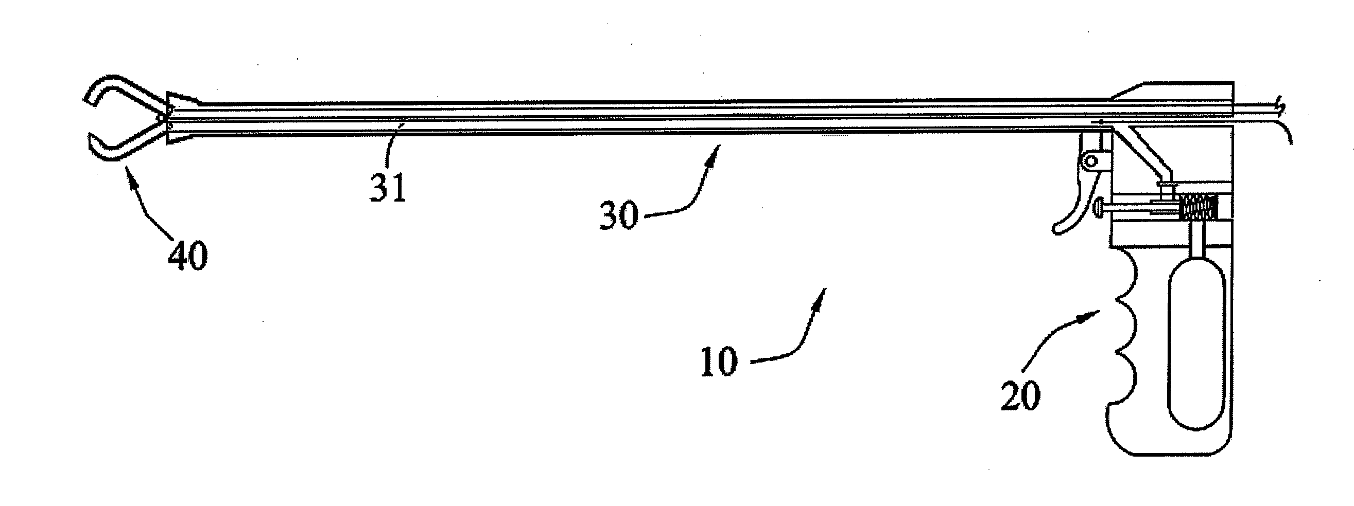
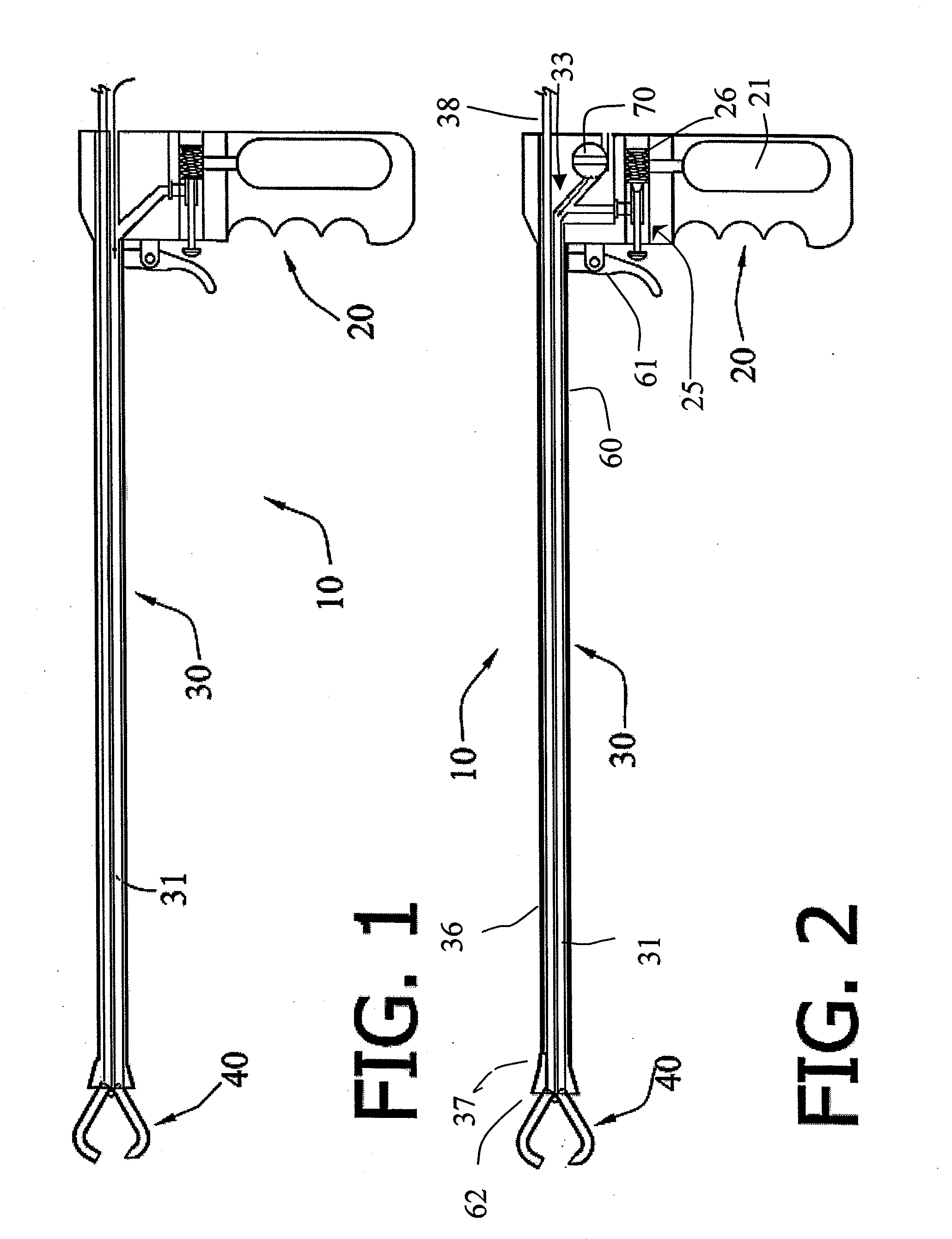
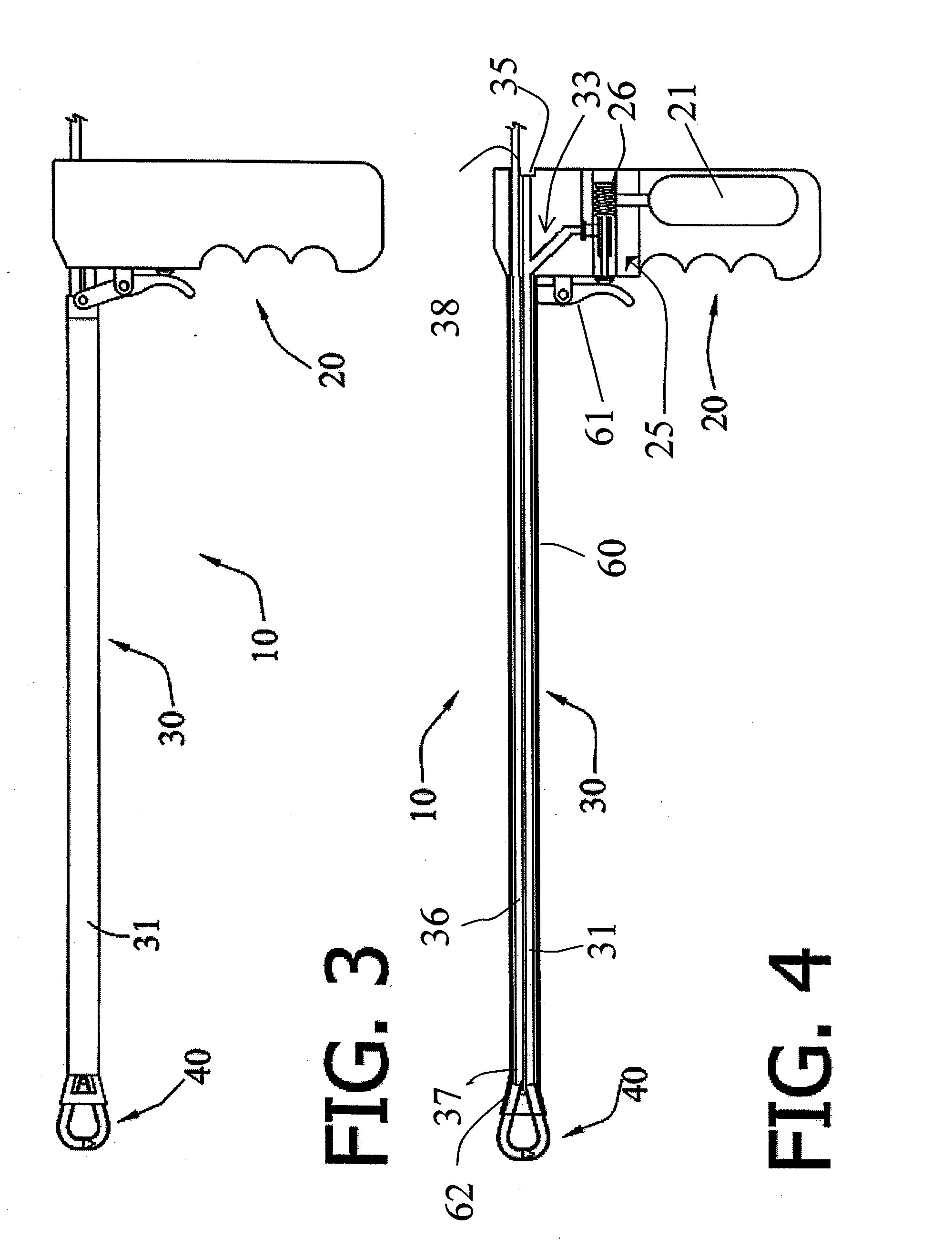
[0043] In reference to the drawings, the suture instrument 10 of the present invention comprises a handle portion 20, an elongated tubular member 30 extending from handle portion 20 and a hollow tissue penetrating needle 40 located at an end of elongated tubular member 30 distal handle portion 20. The length of elongated tubular member 30 is selected to correspond with a desired penetration depth within a body to reach the tissues to be joined 11 by a suture 50. The tissues to be joined 11 will also be referred to herein as site of interest. As is well known in the art, a cannula 12, such as that depicted in FIG. 18, is often used to retract the tissues at the entry incision 13 and improves access to the site of interest 11 by retracting the tissues overlying the site of interest 11. Cannula 12 will also perform a protective role for the overlying tissues by preventing undesirable instrument contact with the same. Accordingly, the length of elongated tubular member 30 must also acco...


PUM


Abstract

The surgical suturing instrument incorporates a pressurized fluid suture feed system for passing a suture through the instrument and the tissues to be joined thereby. A fluid jet in communication with a suture feed conduit selectively entrains a suture in a stream of pressurized fluid, which carries the suture through the instrument's hollow tissue penetrating needle. The tissue penetrating needle may be shaped to direct the suture's free end to a point external the body cavity. Alternatively, a suture return conduit may be provided to engage the hollow tissue penetrating needle to receive and carry the suture's leading end to a point external the body cavity. External or internal pressurized fluid sources are utilized. A surface irregularity proximal the suture's leading end enhances the entrainment of the suture with the fluid stream. Individual, cartridge and spool fed sutures may all be utilized.

Description

TECHNICAL FIELD [0001] This invention relates to the field of suturing instruments used for stitching internal tissues of the body, such as in arthroscopic or endoscopic surgery. More particularly, the invention relates to a suturing instrument wherein the suture is fed through the instrument and the tissues to be joined by entrainment with a pressurized fluid. The preferred suture contemplated by the invention will have a surface irregularity to provide an enhanced frictional interface to facilitate entrainment in the fluid stream. BACKGROUND OF THE INVENTION [0002] In the field of arthroscopic surgery various suturing instruments have been used 11 for stitching internal tissues of the body. An object of such surgical procedures is to minimize the invasiveness of the surgical instrument in performing a given surgical procedure, whether diagnostic or restorative. This object is achieved by making a small incision in the overlying tissue layers to provide the surgeon access the site ...

Claims


Application Information

Patent Timeline
Patent Type & Authority Applications(United States)
IPC IPC(8): A61B17/04
CPCA61B17/0469A61B17/06119A61B17/06166A61B2017/06176A61B2017/0472A61B2017/0479A61B2017/00535
Inventor FARRIS, ALEX F.
Owner FARRIS ALEX F
Why Eureka
Eureka Blog
Learn More