Boat pad and boat pad assembly

a technology for boats and pads, applied in the field of boats, can solve the problems of limited life expectancy of pads, wood pads that contact the boat bottoms typically scratch and/or otherwise damage these boat bottoms, and the painted wood surface typically does not provide sufficient protection for the boat bottoms

Inactive Publication Date: 2006-01-12
ARGITIS JOHN J
View PDF17 Cites 2 Cited by
  • Summary
  • Abstract
  • Description
  • Claims
  • Application Information

AI Technical Summary

Benefits of technology

[0008] An example embodiment of the present invention is directed to a boat pad. The boat pad may include a generally planar member composed of an elastomeric, rubber or like material. The planar member may include a plurality of spaced-apart raised features formed on a surface thereof. The raised features may be configured to contact a surface of a water vessel hull as the hull is being supported by a boat stand or boat trailer including the pad.
[0009] Another example embodiment of the present invention is directed to a boat pad assembly. The boat pad assembly may include a boat pad composed of a generally planar member and having a plurality of spaced-apart raised features formed on a facing surface thereof, and a backing plate to which a back surface of the boat pad is attached. The pad and backing plate may form a boat pad assembly that is removably attachable to a boat stand or boat trailer, so that the raised features on the facing surface contact a surface of a water vessel hull as the hull is being supported by the boat stand or boat trailer including the boat pad assembly.
[0010] Another example embodiment of the present invention is directed to a boat stand. The boat stand may include a boat pad assembly. The boat pad assembly may comprise a generally planar member having a plurality of spaced-apart raised features formed on a facing surface thereof, and a backing plate to which a back surface of the boat pad is attached. The stand may further include an upper portion to which the boat stand assembly is removably attached, a central support member adapted to support the upper portion with boat pad assembly, and a plurality of support legs extending from the central support member. The boat pad assembly may be oriented so that the raised features on the facing surface contact a surface of a water vessel hull as the hull is being supported by the boat stand.
[0011] Another example embodiment of the present invention is directed to a boat trailer. The trailer may include a frame on which wheels are mounted. The frame may include a pair of spaced beams running lengthwise with either side connected by a plurality of cross-bars. A plurality of boat pad assemblies may be arranged in spaced relation and removably attachable to the frame for supporting a water vessel thereon. Each given boat assembly may include a generally flat planar member having a plurality of spaced-apart raised features formed on a facing surface thereof, and a backing plate to which a back surface of the boat pad is attached. Each given boat pad assembly may be oriented so that the raised features on the facing surface contact a surface of a water vessel hull as the hull is being supported by the boat trailer.

Problems solved by technology

The painted wood surface typically does not provide sufficient protection to boat bottoms.
The painted wood pads that contact the boat bottoms typically scratch and / or otherwise damage these boat bottom surfaces.
Another problem with the use of wood pads is the limited life expectancy of the pads, since the nature of the material used lends itself to decay over a relatively short period of time and hence requires periodic repair and / or replacement.
The problem with using carpeting is that the carpeting acts as a sponge, holding moisture against the boat hull and the wood pad itself.
This typically causes the portion of the boat hull or bottom contacting the pad to blister over time, and can expedite the decay process of the wood pad.
The replacement of the wood pads thus poses an expensive problem for boat owners and / or users.
None of these prior art methods effectively protect the boat bottoms from scratches, blemishes, rub marks and damage.
Additionally, none of these prior art solutions effectively prolong the life of the pad itself, with some actually serving to reduce the life of the wood pad.

Method used


Image

  • Boat pad and boat pad assembly
  • Boat pad and boat pad assembly
  • Boat pad and boat pad assembly

Examples


Embodiment Construction

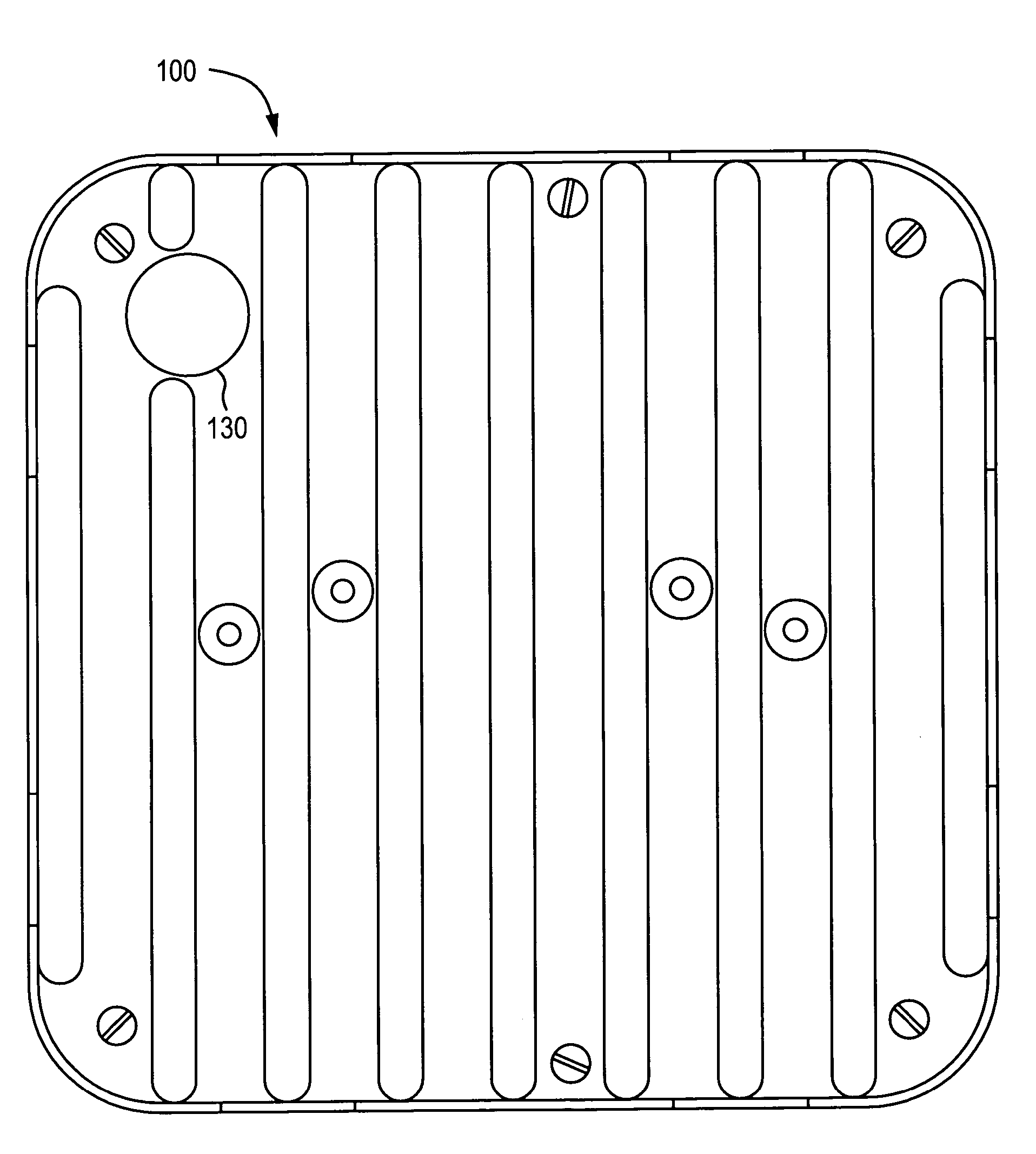
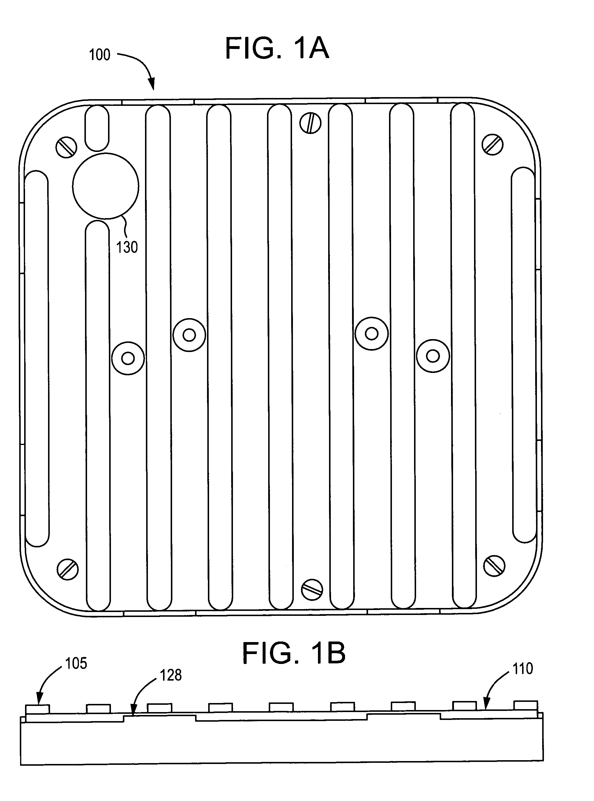
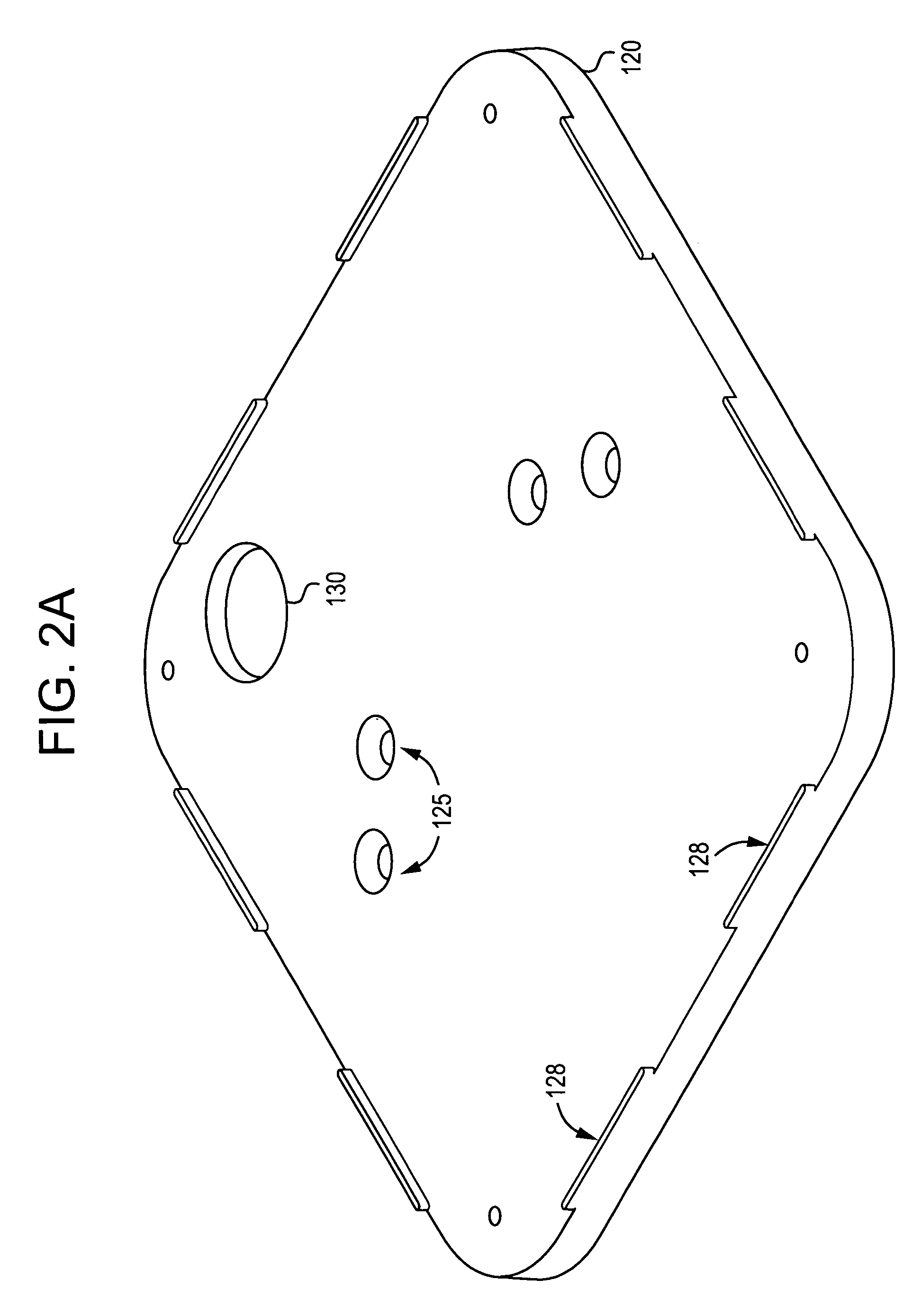
[0022]FIG. 1A through 2C illustrate a boat pad and boat pad assembly for use with a boat stand and / or boat trailer in accordance with the example embodiments; these figures should be frequently referred to for the following discussion.

[0023] Referring to FIG. 2B, there shown is a boat pad 101 which may be configured in any desired size so as to fit on a suitable backing plate member (which forms an upper portion of a typical boat stand, for example). In the example of FIG. 2B, boat pad 101 includes a generally flat planar member, and may include a plurality of raised features or ribs 105 thereon. Ribs 105 may be arranged in parallel in adjacent spaced relation on a surface of the planar member so as extend longitudinally along the pad facing surface, as shown. This arrangement may define a plurality of recesses or channels 110 there between, as shown best in FIG. 1B.

[0024] Pad 101 may be ultraviolet resistant and chemical resistant and composed of an elastomeric, rubber or like ma...


PUM


Abstract

A boat pad may include a planar member composed of an elastomeric, rubber or like material. The planar member may include a plurality of spaced-apart raised features formed on a surface thereof and which are configured to contact a surface of a water vessel hull as the hull is being supported by a boat stand or boat trailer including the pad.

Description

CROSS-REFERENCE TO RELATED APPLICATIONS [0001] This application claims priority under 35 U.S.C. §119(e) to U.S. Provisional Patent Application Ser. No. 60 / 586,413, filed Jul. 9, 2004 to John J. Argitis and entitled “BOAT PAD FOR BOAT STAND”, the entire contents of which is hereby incorporated by reference herein.BACKGROUND OF THE INVENTION [0002] 1. Field of the Invention [0003] The present invention relates generally to a boat pad and / or a boat pad assembly for a boat stand and / or a boat trailer. [0004] 2. Description of the Related Art [0005] Conventionally, boat pads for boat stands and / or boat trailers have been constructed with a painted wood platform (approximately 12 in.×12 in. sq.) that is coated (i.e., dip painted). The painted wood surface typically does not provide sufficient protection to boat bottoms. For example, many racing sailboats have epoxy bottoms or bottoms having a wet sanded gel coat. The painted wood pads that contact the boat bottoms typically scratch and / or...

Claims


Application Information

Patent Timeline
Patent Type & Authority Applications(United States)
IPC IPC(8): B63B17/00
CPCB60P3/1066B63B23/66B63C5/02B63C3/12B63C1/00
Inventor ARGITIS, JOHN J.
Owner ARGITIS JOHN J
Why Eureka
Try Eureka