Method for producing thermoplastic resin laminated sheet

Inactive Publication Date: 2006-01-12
SUMITOMO CHEM CO LTD +1
View PDF2 Cites 6 Cited by
  • Summary
  • Abstract
  • Description
  • Claims
  • Application Information

AI Technical Summary

Benefits of technology

[0006] Thus, the inventors of the present application have made intensive studies so as to develop a method which is capable of readily producing a thermoplastic resin laminated sheet where in a film (F) is laminated onto a sheet (S) with a sufficient adhesion. As a result, the inventors have found that a laminated sheet in which a film (s) is bonded to a shee

Problems solved by technology

The above production method does not always provide a laminated sheet (A) whi

Method used


Image

  • Method for producing thermoplastic resin laminated sheet
  • Method for producing thermoplastic resin laminated sheet
  • Method for producing thermoplastic resin laminated sheet

Examples


Example

Example 1

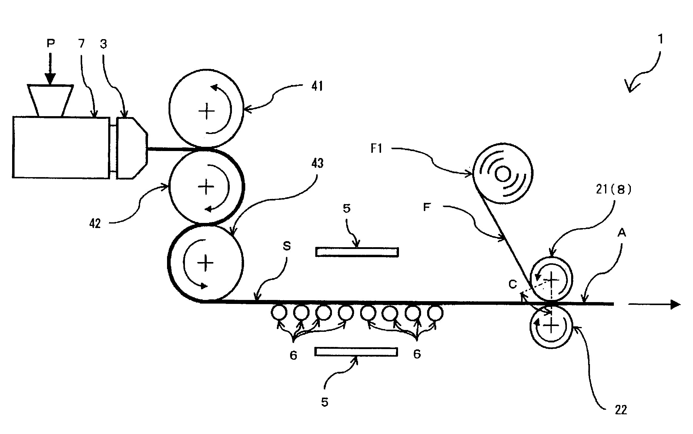
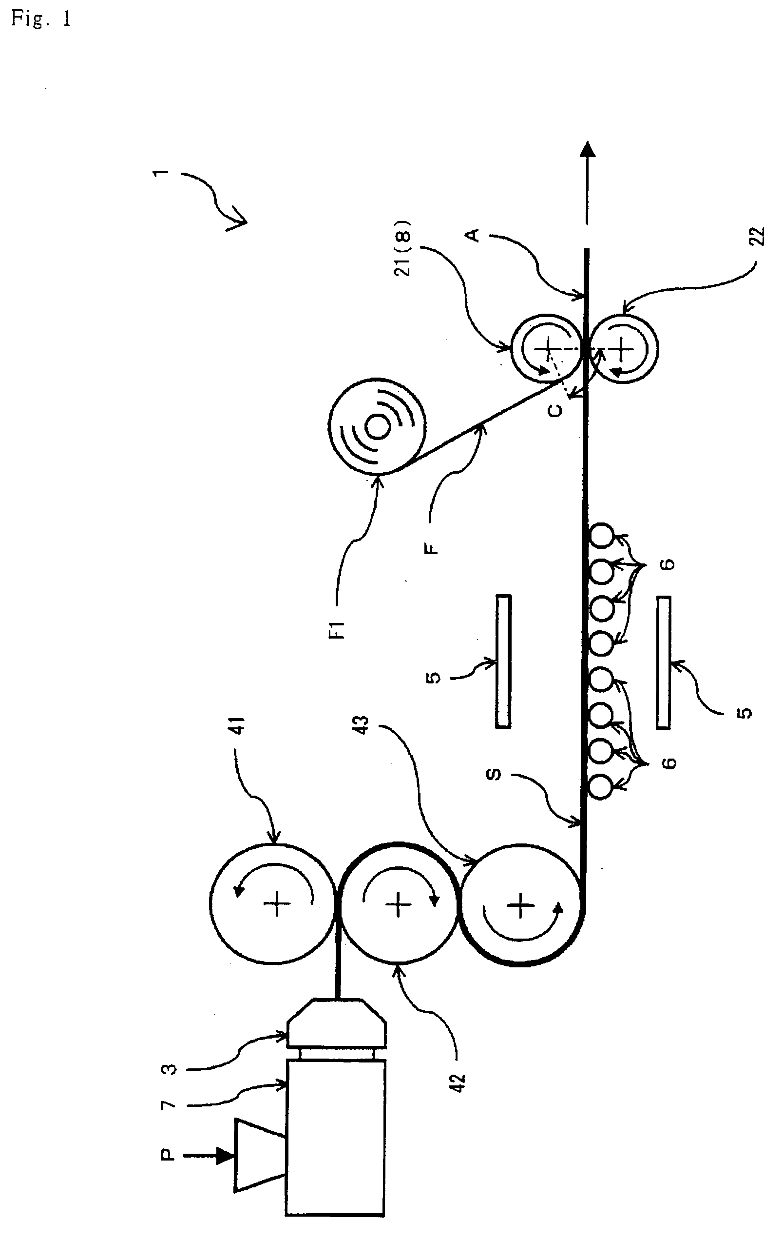
[0079] As shown in FIG. 1, an acrylic resin (P) having a glass transition temperature (Tgs) of 105° C. was heated, melted and kneaded by an extruder (7), and extruded through a die (3), followed by rolling with the three calender rolls (41, 42, 43) each having a diameter of 200 mm, to obtain a continuous acrylic resin sheet (S) having a thickness of 2 mm and a width of 200 mm. Thus obtained sheet (S) was heated from its both surfaces by a far infrared heaters (5) while being held generally horizontally by means of the guide rolls (6), and the sheet (S) was supplied into the gap between a pair of the rolls (21, 22) each having a diameter of 100 mm. The power of the heaters (5) was controlled such that the lamination surface (Sa) of the acrylic resin sheet (S) had a temperature (Ts) of 115° C. just before being sandwiched by the lamination rolls (21, 22).

[0080] On the other hand, an acrylic resin continuous film (F) having a single acrylic resin layer with a glass transitio...

Example

Example 2

[0082] Example 1 was repeated except that the power of the far infrared heaters (5) was controlled such that the lamination surface (Sa) of the acrylic resin sheet (S) had a temperature (Ts) of 120° C. just before being sandwiched by the lamination rolls while the temperature of the roll (21) was controlled such that the lamination surface (Fa) of the acrylic resin continuous film (F) had a temperature (Tf) of 70° C. just before being sandwiched by the lamination rolls, whereby an acrylic resin laminated sheet (A) was produced in which the acrylic resin film (F) was laminated onto one surface (Sa) of the acrylic resin sheet (S). No wrinkle was observed on the film (F) of the laminated sheet (A). As in Example 1, the sheet (A) was cut into the leaves, and the laminated sheet in the leaf form was cut using the electric saw. No delamination of the film (F) was observed across the cut section.

Example

Example 3

[0083] Example 1 was repeated except that the power of the far infrared heaters (5) was controlled such that the lamination surface (Sa) of the acrylic resin sheet (S) had a temperature (Ts) of 130° C. just before being sandwiched by the lamination rolls while the temperature of the rolls was controlled such that an acrylic continuous film (F) having single acrylic resin layer was used which layer had a glass transition temperature (Tgf) of 105° C. and a thickness of 125 μm without surface treatment in place of the film with the glass transition temperature of 80° C., whereby an acrylic resin laminated sheet (A) was produced in which the acrylic resin film (F) was laminated onto one surface (Sa) of the acrylic resin sheet (S). No wrinkle was observed on the film (F) of the laminated sheet (A). As in Example 1, the sheet (A) was cut into the leaves, and the laminated sheet in the leaf form was cut using the electric saw. No delamination of the film (F) was observed along th...


PUM

PropertyMeasurementUnit
Lengthaaaaaaaaaa
Lengthaaaaaaaaaa
Force constantaaaaaaaaaa

Abstract

There is provided a method for producing a thermoplastic resin laminated sheet in which a thermoplastic resin film is bonded to a thermoplastic resin sheet with the sufficient adhesion, and such laminated sheet is obtained by sandwiching the thermoplastic resin film and the thermoplastic resin sheet between lamination rolls while each of their surfaces to be laminated has a temperature within a predetermined specific range, followed by pressing them.

Description

BACKGROUND OF THE INVENTION [0001] 1. Field of the Invention [0002] The present invention relates to a method for producing a thermoplastic resin laminated sheet, and particularly to a method for producing a thermoplastic resin laminated sheet in which a thermoplastic resin film is laminated onto a thermoplastic resin sheet by means of heat-welding. [0003] 2. Description of the Background Art [0004] Japanese Laid-open Patent Publication No. 06-126854 / 1994 discloses a production method of a thermoplastic resin laminated sheet (which is also referred to as merely a “laminated sheet”) (A) as shown in FIG. 5 wherein a thermoplastic resin film (which is also referred to as merely a “film”) (F) is laminated onto one side (as shown in FIG. 4(a)) or each side (as shown in FIG. 4(b)) of a thermoplastic resin sheet (which is also referred to as merely a “sheet”) (S), and such method comprises superimposing, on the sheet (S) in its heated state, the film (F) as it is which is heat-weldable to ...

Claims


Application Information

Patent Timeline
IPC IPC(8): B29C65/00B32B37/00B32B37/14B29C48/08
CPCB29C47/0021Y10T156/1741B29C65/1412B29C65/1422B29C65/1432B29C65/1464B29C66/45B29L2009/00B32B27/30B32B37/0053B32B37/06B32B37/153B32B37/206B32B2309/02B32B2309/12B29C65/1467B29C65/5057B29C65/028B29C66/91413B29C66/91423B29C66/91645B29C65/4815B29C66/91216B29C66/91221B29C47/14B29C66/83413B29C65/7894B29C66/71B29C66/723B29C66/1122B29C66/73117B29C48/08B29C48/305B29K2077/00B29K2069/00B29K2067/00B29K2059/00B29K2055/02B29K2033/12B29K2033/08B29K2027/16B29K2027/06B29K2025/08B29K2025/06B29K2023/12B29K2023/06B32B27/08B32B37/00
Inventor HASE, NORIAKIWATANABE, KOUICHIROUNOJIMA, TAKAYUKI
Owner SUMITOMO CHEM CO LTD
Why Eureka
Try Eureka