
Light Mixing LED

a technology of led light and led light, which is applied in the direction of basic electric elements, electrical equipment, and semiconductor devices, etc., can solve the problems of limiting the lifetime of white leds, high production costs of such light emitting devices, and insufficient light mixing

Inactive Publication Date: 2006-01-12
EPISTAR CORP
View PDF8 Cites 39 Cited by
  • Summary
  • Abstract
  • Description
  • Claims
  • Application Information

AI Technical Summary

Benefits of technology

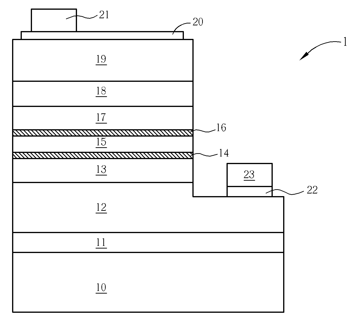
The present invention provides a light mixing LED that can adjust the color of mixed light by changing the thickness of a tunnelable barrier layer to achieve a predetermined color rendering coordinate. The LED comprises multiple active layers of quantum well structure sandwiched between n-type and p-type nitride-based semiconductor stack layers. The first active layer contains In laminated adjacent to the n-type nitride-based semiconductor stack layer, the second active layer contains In laminated adjacent to the p-type nitride-based semiconductor stack layer, and a tunnelable barrier layer is formed between the first and second active layers. The color rendering coordinate of the mixed light is set at a predetermined value in a range between the first and second principal peak wavelengths, which is substantially proportional to the thickness of the tunnelable barrier layer.

Problems solved by technology

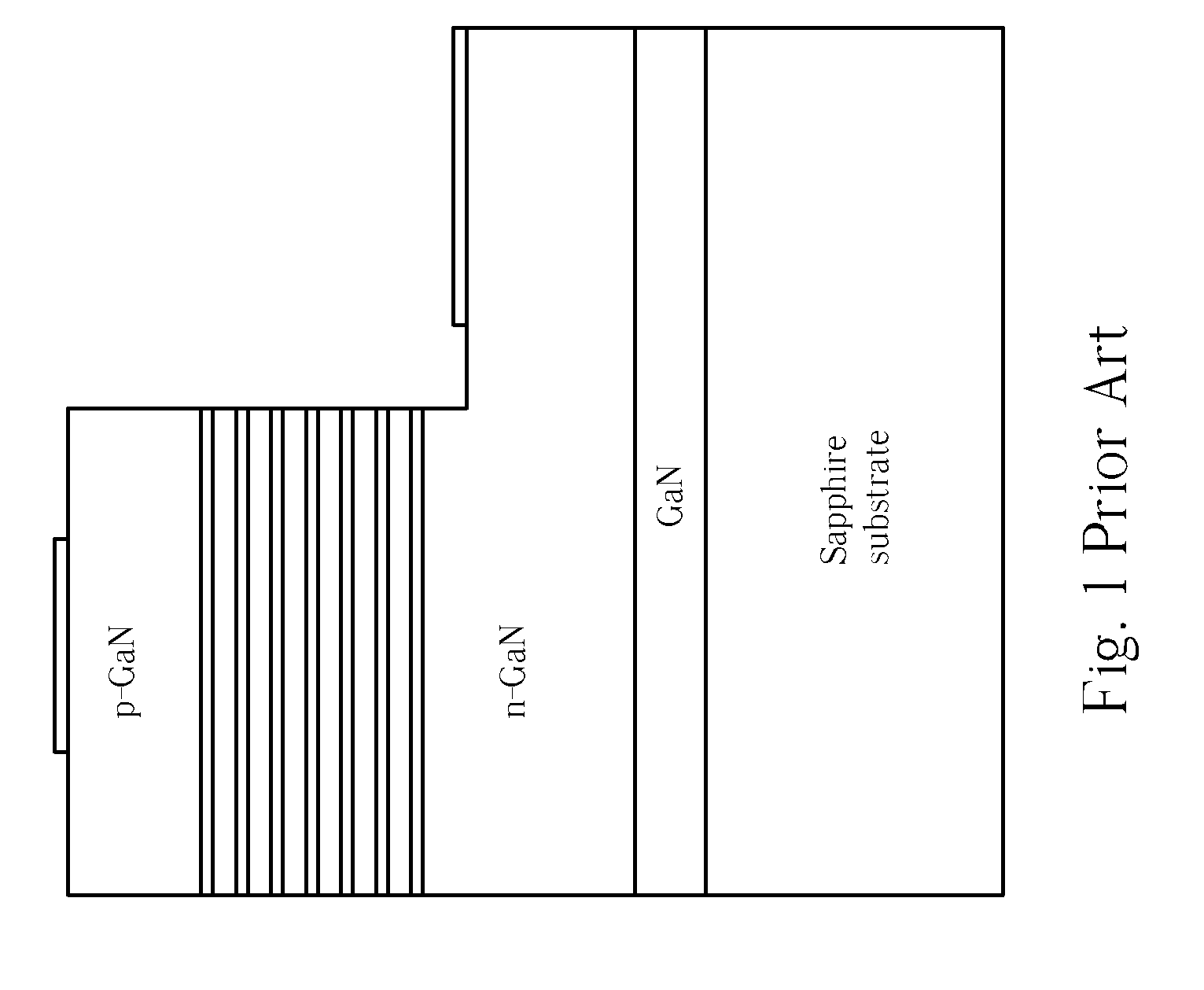
However, the production cost of such light emitting device is high, and the effect of the light mixing is not optimal because the three individual LEDs are not small enough to form a spot light.
However, the lifetime of the yellow phosphor is much shorter than that of the blue LED chip, thus limiting the lifetime of the white LED.
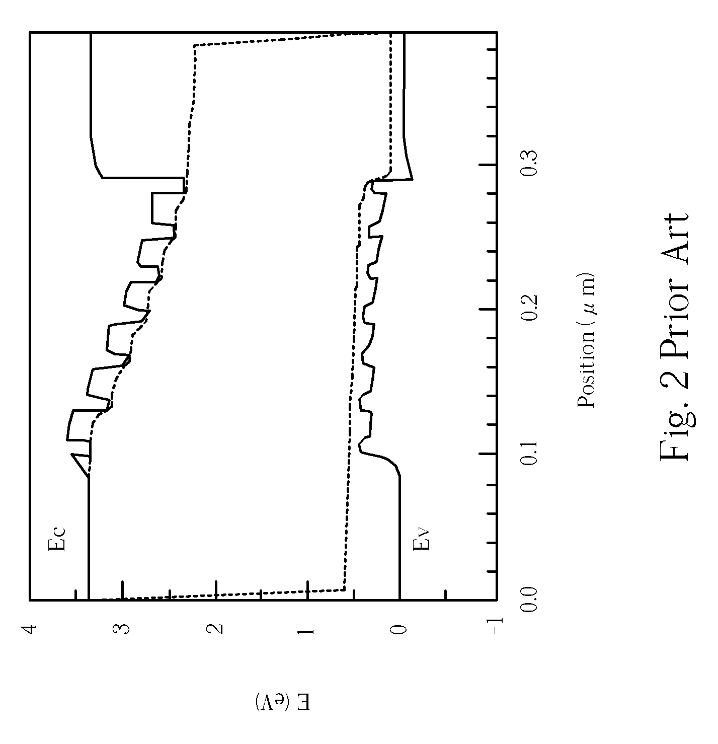
Such thin barrier layers cannot confine the conductive carriers effectively, so the luminance efficiency is inferior.
In addition, if color of the mixed light generated by the LED chips different from the predetermined color, it is hard to adjust wavelengths and intensities of light generated by the quantum well layers because the color and the color rendering index property of the mixed light are related to plenty of parameters (which are complex to analyze), such as compositions, energy bandgaps, and widths of the quantum well layers and of the barrier layers.
As a result, the technique disclosed in JP 11-87773 cannot be utilized for mass production.
However, the above adjustment, by increasing or deceasing pair numbers of corresponding active layers, cannot get a continuous color rendering coordinate, i.e. the LED chip 400 is hard to be fine-tuned to change the color rendering coordinate thereof.
Too many parameters are too complex to control.
In addition, the structure disclosed in U.S. Pat. No. 6,608,330 has another disadvantage.
However the method mention above is uncontinuous and inaccurate, which is too complex and inefficient for mass production.

Method used


Image

  • Light Mixing LED
  • Light Mixing LED
  • Light Mixing LED

Examples


Embodiment Construction

[0033] The present invention decreases complexity of manufacturing a light mixing white LED by forming a tunnelable barrier layer between two active layers of two color lights, and a color rendering coordinate of a mixed light generated by the light mixing white LED can be adjusted continuously and easily in a wide range. In a design of an epitaxial structure, after selecting wavelengths of active layers corresponding to two (or three) colors, a tunnelable barrier layer is formed between the active layers. Then, by adjusting a width of the tunnelable barrier layer, the tunneling probability of conductive carriers passing through the tunnelable barrier layer is changed, and a distribution ratio of conductive carriers in an electro-photo energy conversion is changed accordingly. As a result, intensities of two primary peaks can be adjusted to control a color rendering coordinate continuously and in a wide range.

[0034] As those skilled in the art can understand, in a nitride-based sem...


PUM


Abstract

A light mixing LED includes a first active layer containing In laminated adjacent to an n-type nitride-based semiconductor stack layer, a second active layer containing In laminated adjacent to a p-type nitride-based semiconductor stack layer, and a tunnelable barrier layer formed between the first active layer and the second active layer.

Description

CROSS REFERENCE TO RELATED APPLICATIONS [0001] This is a continuation-in-part of application Ser. No. 10 / 412,306, filed Apr. 14, 2003, which is incorporated in its entirety herein by reference.BACKGROUND OF THE INVENTION [0002] 1. Field of the Invention [0003] The present invention generally relates to a light emitting diode (LED), and more particularly to a light mixing LED. [0004] 2. Description of the Prior Art [0005] Light emitting diodes (LEDs) are employed in a wide variety of applications including optical displays, traffic lights, data storage apparatuses, communication devices, illumination apparatuses, and medical treatment equipment. Among varieties of LEDs, white LEDs are the most important and are in great demand. Fluorescent tubes or lamps that are widely used could be replaced by white LEDs if the manufacturing cost thereof can be reduced and the life thereof can be prolonged. [0006] In conventional, three individual LEDs, such as a red LED, green LED, and blue LED, c...

Claims


Application Information

Patent Timeline
Patent Type & Authority Applications(United States)
IPC IPC(8): H01L29/06
CPCH01L33/08
Inventor OU, CHENHSU, CHEN-KE
Owner EPISTAR CORP
Learn More