Multibeam scanning optical apparatus and multibeam image forming apparatus

a scanning optical apparatus and multi-beam technology, applied in the direction of instruments, printing, etc., can solve the problems of deterioration in the outputted image, inability to use the multi-beam light emitting element array while enjoying its original function, and inability to forming images for photo documents, etc., to achieve the effect of reducing resolution, achieving a small reduction in print productivity and aiming at print productivity

Inactive Publication Date: 2006-01-12
KONICA MINOLTA BUSINESS TECH INC
View PDF2 Cites 2 Cited by
  • Summary
  • Abstract
  • Description
  • Claims
  • Application Information

AI Technical Summary

Benefits of technology

[0022] On the other hand, in the case where the determiner specifies the beam generating elements operating normally and arranged in a continuous row and the aimed print productivity can be achieved even when the system speed is controlled based on the above formula (3) where “m” represents the number of beam generating elements arranged in advance while “a” representing the number of beam generating elements which are operating normally and arranged in a continuous row, the system speed may be controlled based on the formula (3) while the pixel clock frequency and the number of revolutions of the deflector are maintained at the initial values.
[0023] By such control, image forming can be continued by using only the normally operating laser diodes without reducing the resolution. Although the print productivity may be reduced slightly, the aimed print productivity can be achieved.

Problems solved by technology

However, when at least one of the light emitting elements suffers a failure, the use of the multibeam light emitting element array while enjoying its original function is impossible.
In the disclosed apparatus, on the other hand, image forming for a photo document is not allowed when such a failure occurs, because it causes a noticeable defect on the outputted image.
Therefore, even in the case of a text document, deterioration in the outputted image is inevitable.
Further, since the image forming operation cannot be continued in the case of a photo document, the apparatus cannot be used for an urgent matter.
Furthermore, the apparatus cannot address the situation in which a plurality of beams are lacked.
Moreover, the failure in just one of the light emitting elements eventually necessitates the replacement of the scanning optical unit, which is not economical.
Although such control of the system speed reduces the print productivity, image forming can be continued by using only the normally operating beam generating elements without reducing the resolution.

Method used


Image

  • Multibeam scanning optical apparatus and multibeam image forming apparatus
  • Multibeam scanning optical apparatus and multibeam image forming apparatus
  • Multibeam scanning optical apparatus and multibeam image forming apparatus

Examples


embodiment

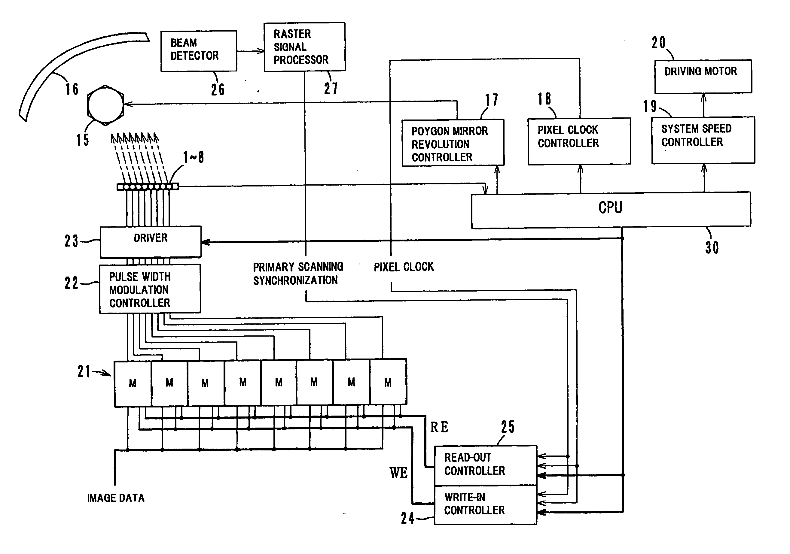
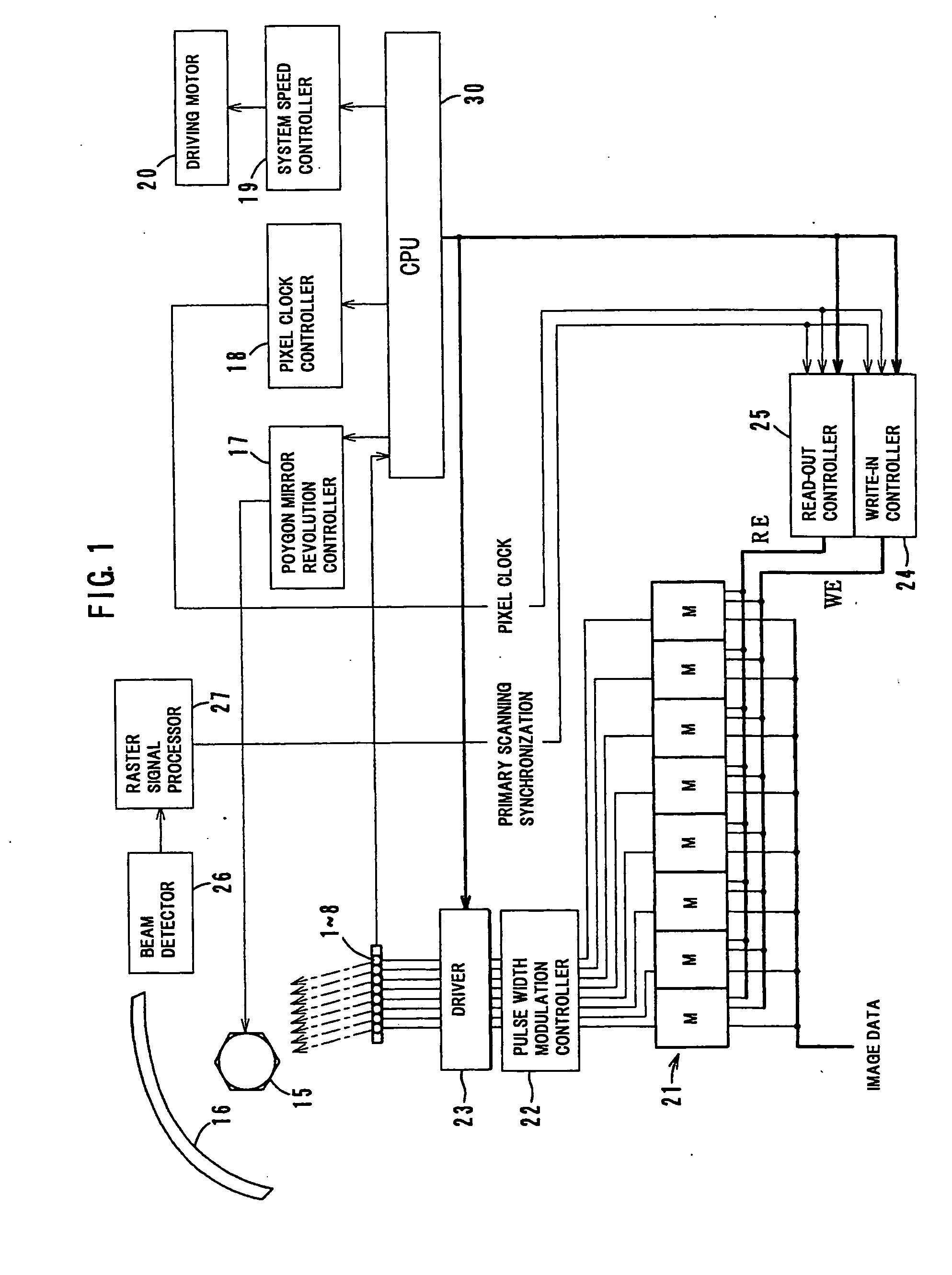
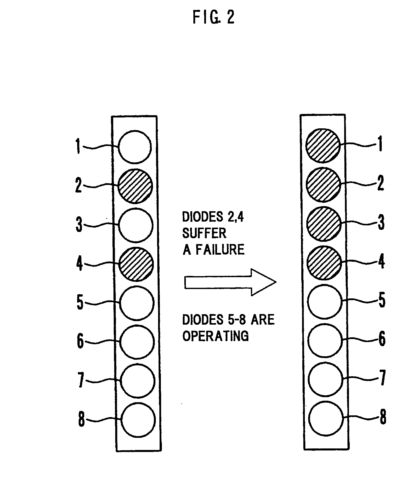
[0056] Herein, as Embodiment 1, the control during emission failure in an image forming apparatus of the spec given in Table 1 below will be described.

TABLE 1Initial number of beams mEightPrint productivity80sheets / min.Initial pixel clock frequency15MHzMaximum rated pixel clock frequency100MHzInitial number of polygon mirror revolutions9900rpmMaximum rated number of polygon mirror45000rpmrevolutionsInitial system speed400mm / sMinimum system speed283mm / s

[0057] With respect to the image forming apparatus of the spec in Table 1, the values after change of the pixel clock frequency and number of polygon mirror revolutions were computed based on the formulae (1), (2), the results of which are given in Table 2 below.

TABLE 2Number ofNumber of beamsPixel clockpolygon mirrorused duringfrequencyafterrevolutionsemissionchangeafter changeSystem speedfailure(MHz)(rpm)(mm / s)717.14113144006201320040052415840400430198004003402640040026039600400

[0058] As will be understood from Table 2, in any of...


PUM


Abstract

A multibeam scanning optical apparatus incluses a controller which specifies laser diodes which are emitting light normally and arranged in a continuous row, a memory having a plurality of area in which image data are stored, a write-in controller which causes image data for each line to be written into only areas of memory corresponding to the specified laser diodes when any of the laser diodes suffers a failure, a read-out controller which causes the image data for each line to be read out simultaneously from the areas of memory corresponding to the specified laser diodes and a driver which performs light emission control only with respect to the specified laser diodes.

Description

[0001] This application is based on Japanese Patent Application(s) No.(s). 2004-200791 filed in Japan on Jul. 7, 2004, the entire content of which is hereby incorporated by reference. BACKGROUND OF THE INVENTION [0002] 1. Field of the Invention [0003] The present invention relates to a multibeam scanning optical apparatus and a multibeam image forming apparatus. It particularly relates to a multibeam scanning optical apparatus and a multibeam image forming apparatus for forming an image on a photosensitive member by irradiating the photosensitive member with a plurality of beams at predetermined intervals in the secondary scanning direction. [0004] 2. Description of Related Art [0005] Recently, in the field of an image forming apparatus utilizing electrophotography, there are provided various multibeam image forming apparatuses for forming an electrostatic latent image on a photosensitive member by using a scanning optical unit incorporating an array of light emitting elements capab...

Claims


Application Information

Patent Timeline
Patent Type & Authority Applications(United States)
IPC IPC(8): H01Q3/22
CPCH01Q3/2676
Inventor NOGUCHI, KAZUYOSHITAKAHAMA, HIDEKAZUTSUTSUMI, TAKAHIROMAEGAWA, TORU
Owner KONICA MINOLTA BUSINESS TECH INC
Why Eureka
Try Eureka