Transflective liquid crystal display with reduced flicker

a liquid crystal display and transflective technology, applied in the direction of instruments, computing, electric digital data processing, etc., can solve the problem that the measurement will only be valid, and achieve the effect of reducing flicker, facilitating dynamic use of backlight, and substantially reducing power consumption

Inactive Publication Date: 2006-01-12
KONINKLIJKE PHILIPS ELECTRONICS NV
View PDF8 Cites 54 Cited by
  • Summary
  • Abstract
  • Description
  • Claims
  • Application Information

AI Technical Summary

Benefits of technology

[0015] In general, the internal voltage for all the reflective sub-pixels will be the same, and the internal voltages for the transmissive sub-pixels will be the same and different from the internal voltage for the reflective sub-pixels. However, there might be some minor differences between the internal voltages for different transmissive sub-pixels, as well as for different reflective sub-pixels. This difference could, for example, be the result of the sub-pixels being exposed to slightly different ambient light intensities. But, for the purpose of reducing flicker, the differences in the internal voltage between sub-pixels of the same type are generally small enough to be neglected. Thus, it is possible to derive a first desired compensation voltage, common to all transmissive sub-pixels, and a second desired compensation voltage, common to all reflective sub-pixels.
[0016] Furthermore, it is envisaged to use an ambient light sensor, sensing the ambient light. Based on the intensity of the ambient light, it is possible to estimate whether a viewer vi

Problems solved by technology

However, since the internal voltages in the two types of sub-pixels generally differ, th

Method used


Image

  • Transflective liquid crystal display with reduced flicker
  • Transflective liquid crystal display with reduced flicker
  • Transflective liquid crystal display with reduced flicker

Examples


Embodiment Construction

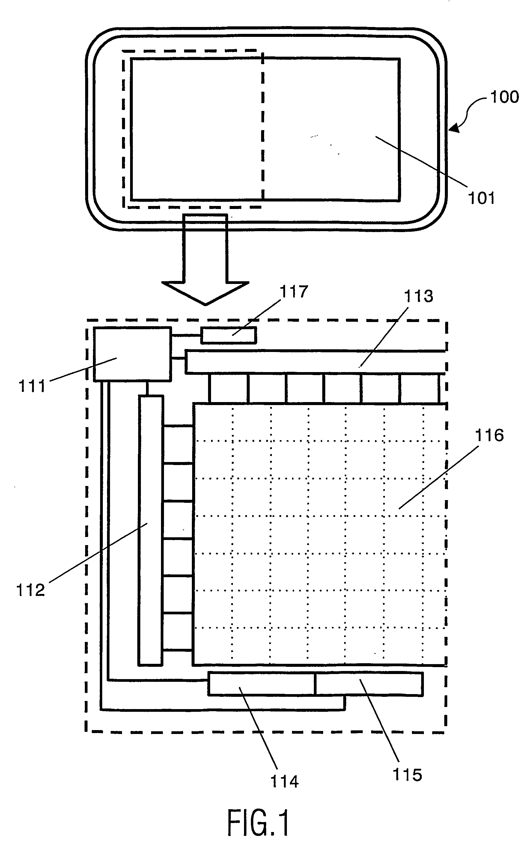
[0042] One preferred embodiment of the present invention is schematically illustrated in FIG. 1, where a transflective display device 100, and an enlarged portion of its display 101 is depicted. The display comprises a web or matrix of transflective pixels, 116, each comprising a transflective sub-pixel and a reflective sub-pixel, which are controlled by electrical circuitry 111 and driven by driver circuitry 112, 113. The driver circuitry 112, 113 comprises a data driver 113 and a row driver 112. The display device 100 further comprises first and second measuring elements, 114, 115. The first measuring element 114 is arranged to output a signal indicative of the internal voltage in the transmissive sub-pixels, the second measuring element 115 is arranged to output a signal indicative of the internal voltage in the reflective sub-pixels. The display device 100 furthermore comprises sensor means 117 for sensing the intensity of ambient light. In an alternative embodiment, in which th...


PUM


Abstract

A method of reducing visible flicker in a transflective display device, having a plurality of pixels, each pixel comprising a transmissive sub-pixel and a reflective sub-pixel, is disclosed. The method comprises the steps of: driving the pixels with an alternating voltage; determining a first desired compensation voltage for the transmissive sub-pixels and a second desired compensation voltage for the reflective sub-pixels; deriving a common compensation voltage from said first desired compensation voltage and said second desired compensation voltage; and applying said common compensation voltage to both the transmissive and the reflective sub-pixels. Thus, the flicker resulting from a DC bias of the driving voltage is substantially reduced. In a preferred embodiment, the method further comprises the steps of: determining a lowest available frame frequency setting for which any remaining flicker is invisible; and setting a frame frequency at which the display is driven to said lowest available frame frequency. According to another embodiment, a backlight is manually controlled and the common compensation voltage is derived as a function of a mode of operation of the backlight. A transflective display device implementing the above methods is also disclosed.

Description

TECHNICAL FIELD OF THE INVENTION [0001] This invention relates to reduction of visible flicker in a transflective display device, such as a liquid crystal display device, comprising a plurality of pixels. BACKGROUND ART [0002] In a transflective display, each pixel comprises a reflective sub-pixel and a transmissive sub-pixel. These displays combine a power-saving, ambient light readable mode in bright environments with a backlit mode in dark environments. Transflective displays are used in, for example, mobile phones, electronic books, electronic organizers, PDA's, notebooks etc. [0003] LCD display devices are usually driven by means of alternating voltages across the pixels, i.e. AC (Alternating Current) driving. Other display types such as electromechanical display types and electrophoretic display types may also be driven by alternating voltages. This is done by driving the pixels, in a first picture frame, with a positive voltage, and in a consecutive picture frame with a negat...

Claims


Application Information

Patent Timeline
IPC IPC(8): G09G5/00G02F1/1335G02F1/133G09G3/20G09G3/34G09G3/36
CPCG09G3/2074G09G3/3406G09G3/3611G09G3/3655G09G2360/144G09G2320/0247G09G2320/029G09G2320/0626G09G2340/0435G09G2300/0456G09G3/36G09G3/20G02F1/133
Inventor VERSCHUEREN, ALWIN ROGIER MARTIJNJOHNSON, MARK THOMAS
Owner KONINKLIJKE PHILIPS ELECTRONICS NV
Why Eureka
Try Eureka