
Environmentally aware, intelligent surveillance device

a technology of intelligent surveillance and environmental awareness, applied in direction finders, instruments, television systems, etc., can solve the problems of many video surveillance systems not having the functional capabilty to fuse disparate data, many existing video processing systems do not produce results that correlate, and many video surveillance systems are not environmentally awar

Inactive Publication Date: 2006-01-12
SIEMENS SWITZERLAND
View PDF5 Cites 210 Cited by
  • Summary
  • Abstract
  • Description
  • Claims
  • Application Information

AI Technical Summary

Benefits of technology

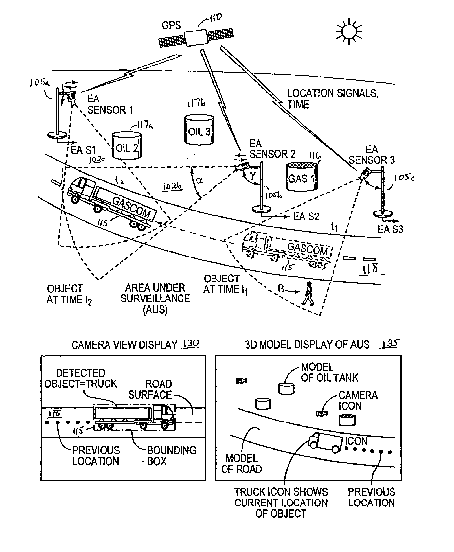
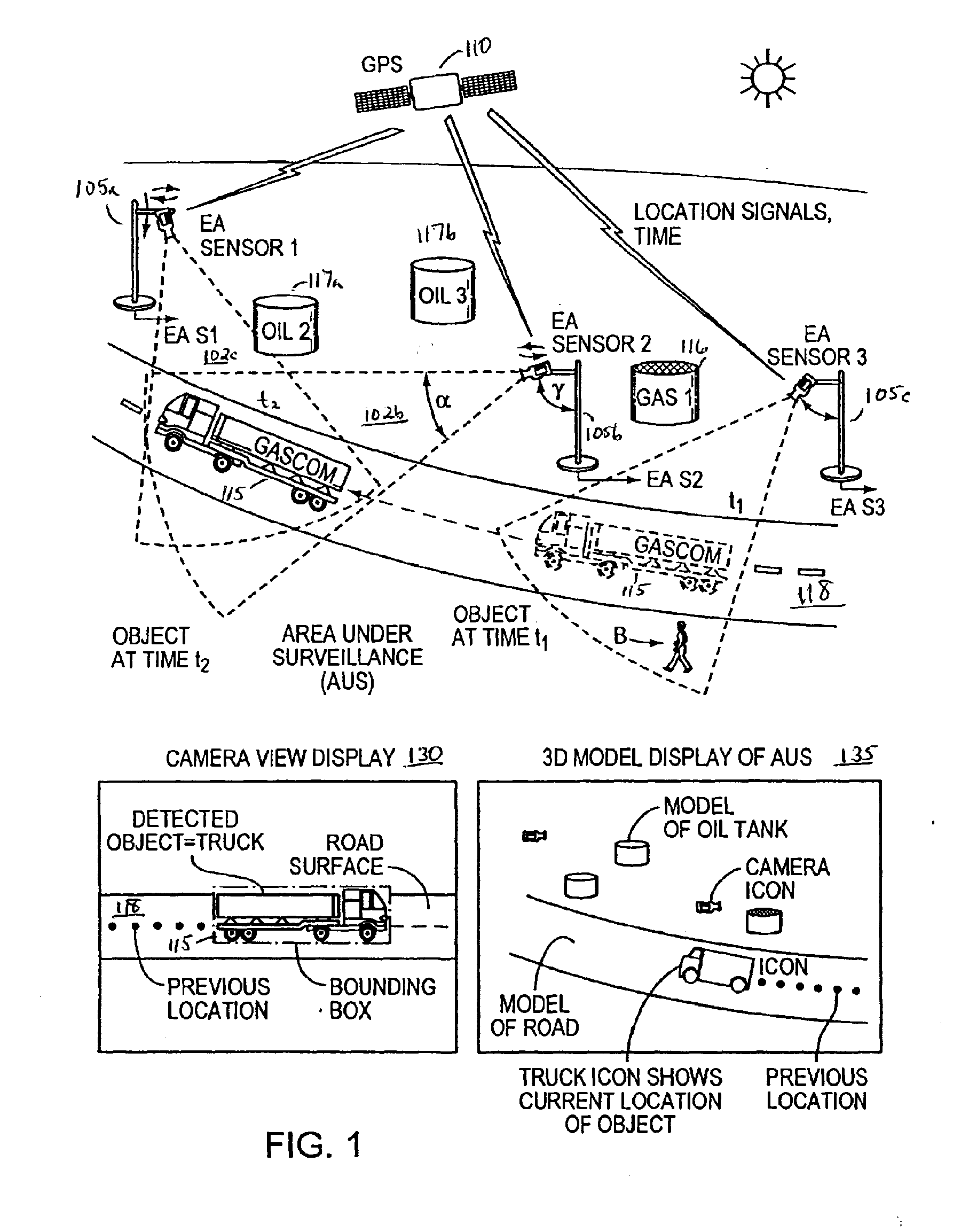
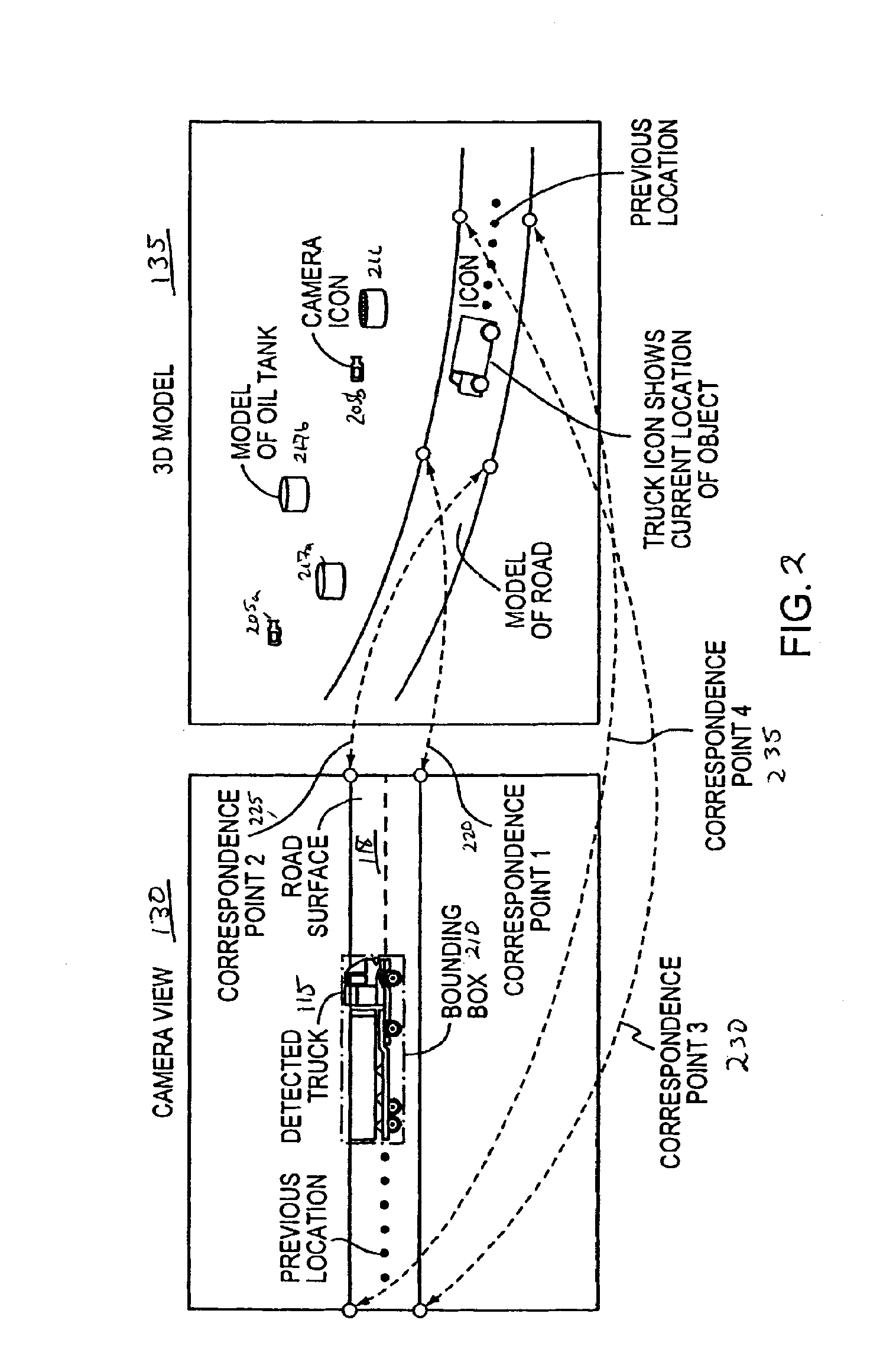
The present invention relates to an environmentally aware surveillance device that uses video technology to observe and record objects in an area under surveillance. The device has the ability to self-determine its position and orientation relative to a real-world spatial and temporal coordinate system, and to generate event information that includes attributes of objects detected by the device. The event information is consistent from surveillance event to event. The device can also track the movement of objects within the area under surveillance and identify specific behaviors of those objects. The invention allows for the mapping of objects to a 3D model and the output of video frames and event record data for external utilization.

Problems solved by technology

Currently, many video cameras or video-type sensors are not environmentally aware.
Numerous existing video processing systems do not produce results that correlate to real world coordinate systems.
Many video surveillance systems do not have the functional capabilty to fuse disparate information into a single situational awareness framework.
While there are systems that do have this capability, they are either highly expensive, custom built systems or they require substantial manual configuration in order to create environmental location data for video information.

Method used


Image

  • Environmentally aware, intelligent surveillance device
  • Environmentally aware, intelligent surveillance device
  • Environmentally aware, intelligent surveillance device

Examples


Embodiment Construction

[0033] One or more exemplary embodiments of the invention are described below in detail. The disclosed embodiments are intended to be illustrative only since numerous modifications and variations therein will be apparent to those of ordinary skill in the art. In reference to the drawings, like numbers will indicate like parts continuously throughout the views.

DEFINITION OF TERMS

[0034] Area Under Surveillance—an area of the real world that is being observed by one or more sensors.

[0035] Camera Sensor—a device that observes electromagnetic radiation and produces a two-dimensional image representation of the electromagnetic radiation observation.

[0036] Camera Image Frame—a two-dimensional image produced by a camera sensor.

[0037] 2D Location—a location in a camera image frame; also referred to as screen coordinates as a camera image frame is frequently displayed on a video screen.

[0038] Video Sensor—a camera sensor that makes periodic observations, typically having a well-defined ...


PUM


Abstract

The present invention relates to methods and systems for the remote monitoring and sensing of a remote deployable, stand-alone, environmentally aware surveillance sensor device or unit that is capable of self-determining its location and orientation relative to a real world, 3D environment, detect conditions or events within the sensor's range of detection within that environment, and provide event information indicative of detected conditions or events including their location relative to the 3D real world environment as well as the raw sensor data feed to an external utilization system such as a security monitoring system. The exemplary sensor unit obtains position information from a position information source, orientation information from an orientation information source and time information, thereafter the unit processes the sensor feed to detect objects and types of objects, and provides event information or information output to an external utilization system such as a security monitoring system.

Description

[0001] This application is a continuation-in-part of U.S. patent application entitled “Environmentally Aware, Intelligent Surveillance Device,” filed Jul. 12, 2004, and assigned Ser. No. 10 / 889,224, the disclosure of which is incorporated herein by reference in its entirety. [0002] This application also claims the benefit, pursuant to 35 U.S.C. §119(e), of U.S. Provisional Patent Application entitled “ENVIRONMENTALLY AWARE, INTELLIGENT SURVEILLANCE DEVICE,” filed on Jul. 11, 2003, and assigned Ser. No. 60 / 486,766, the disclosure of which is incorporated herein by reference in its entirety. [0003] The applicant expressly reserves the right to claim priority to U.S. patent application Ser. No. 10 / 676,395 filed Oct. 1, 2003, entitled “SYSTEM AND METHOD FOR INTERPOLATING COORDINATE VALUE BASED UPON CORRELATION BETWEEN 2D ENVIRONMENT AND 3D ENVIRONMENT,” the disclosure of which is incorporated herein by reference in its entirety. CROSS-REFERENCE TO RELATED APPLICATIONS [0004] This applic...

Claims


Application Information

Patent Timeline
Patent Type & Authority Applications(United States)
IPC IPC(8): H04N7/18H04N9/47
CPCG01S3/7864G06K9/00771G06T7/0018G06T7/0042G08B13/19608H04N7/181G08B13/19663G08B13/19697G08G1/04H04N5/23206G08B13/19645G06T7/80G06T7/73G06V20/52H04N23/661H04N23/61H04N23/635
Inventor IDE, CURTIS EVANJACKSON, JOHNMCGONNIGLE, GLENN MATTHEW
Owner SIEMENS SWITZERLAND
Learn More