
Method and system for switching between video modes in consumer electronics

a technology of consumer electronics and video modes, applied in the field of consumer electronics dvd players and recorders, can solve the problems of user loss of video image output, no longer seeing the gui, and no longer being able to use the graphical user interface, dvd player or other consumer device defective, etc., to achieve the effect of eliminating the need for new hardware and improving customer satisfaction

Inactive Publication Date: 2006-01-12
MAGNUM SEMICONDUCTOR
View PDF22 Cites 24 Cited by
  • Summary
  • Abstract
  • Description
  • Claims
  • Application Information

AI Technical Summary

Benefits of technology

[0012] The system thus prevents and corrects for the cases where a user selects an inappropriate video output. In addition, a user-friendly interface, which results in better customer satisfaction, is provided. Moreover, while some minor software changes to the operating system of the consumer electronic video device (e.g., DVD player) may be required, the need for new hardware may be eliminated.

Problems solved by technology

Since most consumers typically did not move from one locale to another locale, manufacturing a consumer electronic video device capable of multiple output formats was not considered necessary or economical.
Because of the limitations in the number of video DACs (Digital to Analog Converters) in a DVD processor, many DVD players can output either in progressive scan mode or in interlaced scan mode but not both modes simultaneously.
This is generally not a problem, except that if a user selects a mode (e.g., progressive scan) not supported by their monitor or television, and the television does not support it, the user may lose the video image output and can no longer see the GUI (Graphical User Interface) which would allow the user to switch back to the previous mode.
Similarly, if a consumer selects an output that the TV set is not connected to, the screen may go blank, and the consumer will see no image, and may believe that the DVD player or other consumer device is defective.
This problem has led to a large number of warranty returns for consumer electronic devices in the past.
This problem is costly for the manufacturer, as the units are not broken or defective, but merely set to operate in a mode that the user's monitor or TV does not support.
This solution is expensive to implement and adds to the number of plugs on the back of a DVD player.
If the consumer presses the button out of curiosity, inappropriate results may occur (output switches between modes when not desired).
Moreover, putting an extra button on the remote control contributes to the crowding of buttons on the remote unit and also increases cost and complexity of the unit.
In addition to the aforementioned problems, with the advent of HDTV, further modes of operation may be possible, which may be incompatible with various television displays.
Thus, the opportunity for a consumer to generate an output mode, which results in a blank screen or a garbled display increases.
In the past, this situation has been serious.
As noted above, it has led to warranty returns of consumer electronics products.
A consumer may inadvertently switch to an unsupported mode, which results in a garbled or blank display.
Since the consumer cannot now navigate the GUI menu system to return to the previous display mode, the consumer product is now useless.
WINDOWS™ software confronts a similar problem.
However, not all VGA monitors and displays may support all formats and resolutions.
Consumer products, such as DVD players, generally do not have such a reboot option.

Method used


Image

  • Method and system for switching between video modes in consumer electronics
  • Method and system for switching between video modes in consumer electronics
  • Method and system for switching between video modes in consumer electronics

Examples


Embodiment Construction

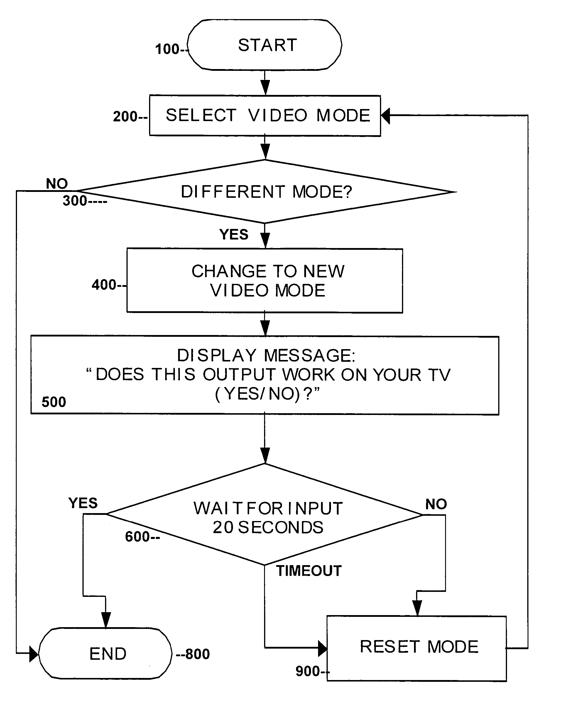
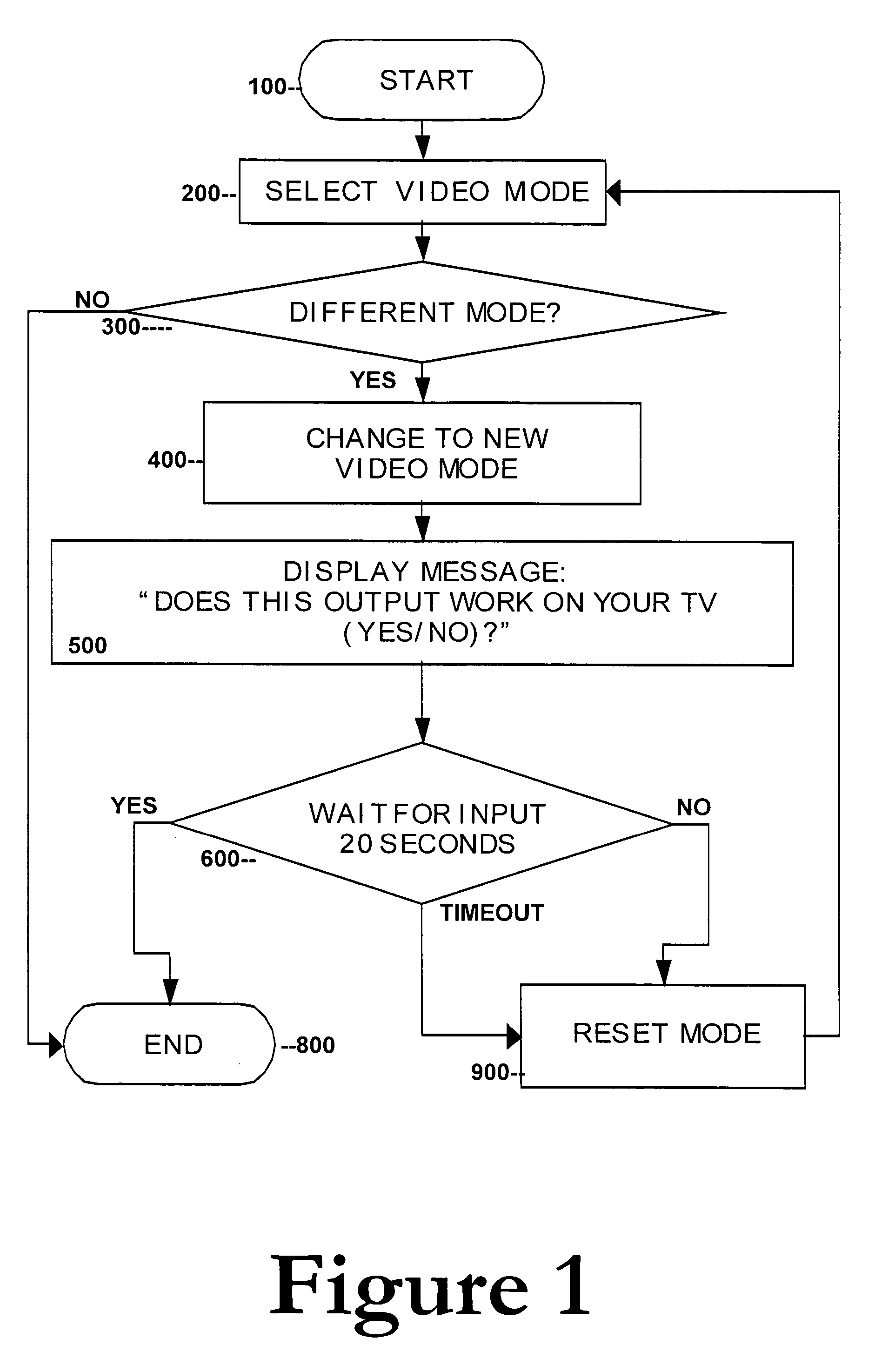
[0015] Referring to FIG. 1, a process is described for selecting different video output modes for a consumer device. This process may represent a subroutine on microprocessor software or firmware running on a consumer electronic device such as a DVD player or player / recorder, or the like. For purposes of illustration, the process begins at block 100 which may represent a branching from an overall program used to operate the consumer electronic device.

[0016] At block 200, a user selects a video mode, preferably from a menu displayed on a setup screen or option screen or the like, displayed on a television display connected to the consumer video device. The user selects a video mode from a menu containing a list of possible output modes by scrolling down the list and selecting one option using the OK or ENTER key on the remote control or on the control panel of the consumer electronic device. As noted above, examples of such different video modes may include, but are not limited to, ...


PUM


Abstract

DVD players and the like may support multiple video formats, including interlaced and progressive scan video. If a user selects a mode (e.g., progressive scan) not supported by their monitor or television, then the user may lose the video image output, and can no longer see the GUI (Graphical User Interface) which would allow the user to switch back to the previous mode. The present invention solves this problem by providing a method and system whereby a new display mode or resolution is generated and a message displayed requesting the user to confirm whether the resultant display is acceptable. If the user does not respond to the message after a predetermined period of time (e.g., 20 seconds), then the system reverts back to the previous resolution or mode. The system thus prevents and corrects for the cases where a user selects an inappropriate video output. In addition, a user-friendly interface, which results in better customer satisfaction, is provided. Moreover, while minor software changes to the operating system of the consumer electronic video device (e.g., DVD player) may be required, the need for new hardware is eliminated.

Description

CROSS-REFERENCE TO RELATED APPLICATIONS [0001] The present application claims priority from Provisional U.S. Patent Application No. 60 / 585,072, filed on Jul. 6, 2004, and incorporated herein by reference.FIELD OF THE INVENTION [0002] The present invention relates to DVD players and recorders and other consumer video electronics. In particular, the present invention is directed toward a method and apparatus for switching between different video output modes in a consumer video electronic device. BACKGROUND OF THE INVENTION [0003] In the Prior Art, consumer electronic video devices were generally provided with a limited number of output modes. For example, a typical VCR may have been provided with a 75 Ohm coaxial cable connection which would provide NTSC video modulated on a selectable channel (e.g., channel 3 or 4). With the advent of more sophisticated consumer television monitors, other outputs are being provided, including composite video as well as S-video connectors. For most o...

Claims


Application Information

Patent Timeline
IPC IPC(8): H04N3/27
CPCH04N5/46H04N21/4854H04N9/642H04N7/012
Inventor DOUANGPHACHANH, PHANTHAVONG
Owner MAGNUM SEMICONDUCTOR
Learn More