

Device and method for x-ray scatter correction in computer tomography
a computer tomography and scatter correction technology, applied in tomography, applications, instruments, etc., can solve the problems of x-ray scatter generated in objects, significant deterioration of quantitative tissue density reconstruction, and artifact production, and achieve simple scatter correction calculation, low discrete local resolution, and simplified parameter setting.
- Summary
- Abstract
- Description
- Claims
- Application Information
AI Technical Summary
Benefits of technology
Problems solved by technology
Method used
Image

Examples
embodiments
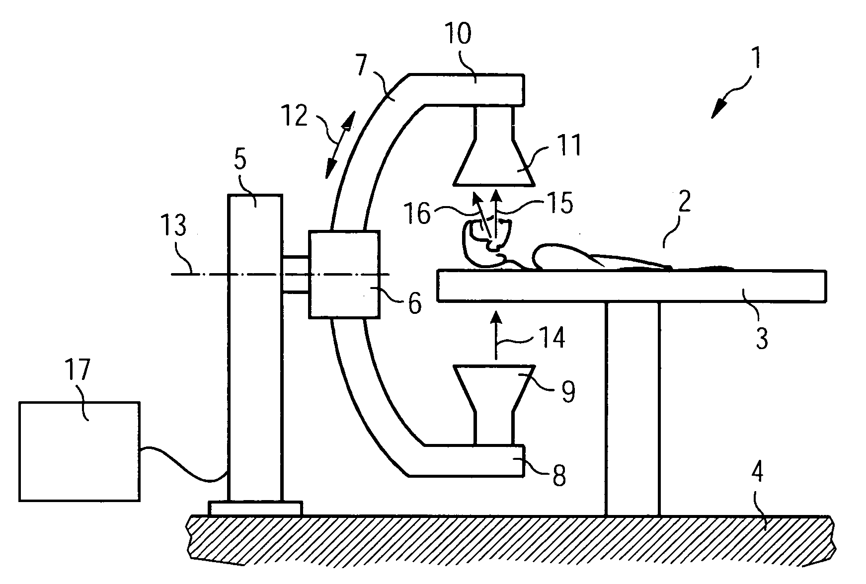
[0148] The x-ray scatter correction described here can be employed with the following computer tomography devices (CT): CT with multi-row detector, CT with flat-panel detector (=FPD), angiography CT with C-arm and x-ray image amplifier or FPD, mobile C-arm CT with x-ray image amplifier or FPD.
embodiment 0
[0149] We will refer to the basic x-ray scatter correction method already described in detail as embodiment 0.
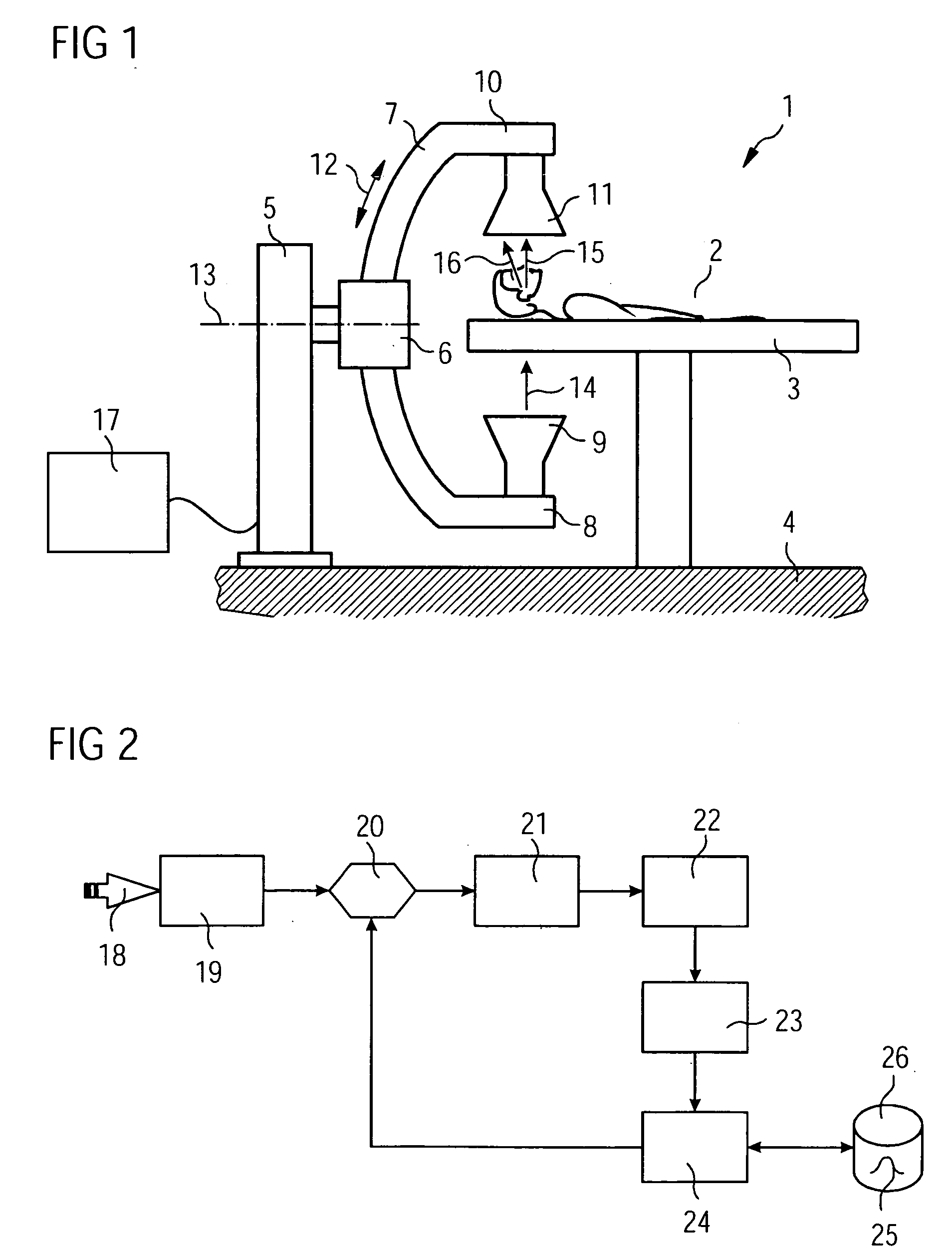
[0150] Embodiment 0 is shown again in detail in FIG. 5. Data recording 18 leads to projection images 19 to which scatter correction 20 will be applied. An image reconstruction 21 produces a volume image 22. The volume image 22 is subjected to a coarsening 38 which leads to a scatter model 23. The coarsening 38 corresponds to the processing step (1) in which the number of voxels 31 and of detector pixels 32 has been decimated. The coarsening 38 leads to the scatter model 23 on the basis of which the scatter data calculation can be performed. A first processing section 39 comprises the processing steps (2) to (4) described above and leads to a lookup 40 in the SBF atlas stored in data memory 26. The SBFs 25 of the scatter data calculation 24 stored in the SBF atlas are made available by reading them out 41. If necessary interpolation is performed between the stored SBFs 25. I...
embodiment 1
[0154] First the CBCT reconstruction is performed on the original possibly fine voxel- and detector pixel grid and for all projection directions.
[0155] The x-ray scatter is then corrected in accordance with embodiment 0 up to and including processing step (8a), with the transition to the original fine pixel grid having been completed in step (7).
[0156] The volume reconstruction in the processing step(9) however, unlike in embodiment 0, is only performed with a small number of projections. The number of projections can for example be reduced by a factor of 4. A greater reduction factor may also possibly be permitted. If the reconstruction of the uncorrected projection data with the reduced number is also available, an x-ray scatter correction volume is produced from the difference between corrected and uncorrected volume.
[0157] Finally this x-ray scatter correction volume is added to the reconstructed (uncorrected) object volume originally corrected with the full projection number...
PUM
 Abstract
Description
Claims
Application Information