
Ring binder mechanism with reinforced hinge plates

a technology of hinge plate and ring, which is applied in the field of ring binder mechanism, can solve the problems of reducing the size of the mounting structure, and reducing the service life of the hinge plate near the end

Inactive Publication Date: 2006-01-12
WORLD WIDE STATIONARY MFG CO LTD
View PDF15 Cites 66 Cited by
  • Summary
  • Abstract
  • Description
  • Claims
  • Application Information

AI Technical Summary

Benefits of technology

[0005] One solution to this problem is to keep the openings relatively small. But with small openings, the size of the mounting structure must be correspondingly small. Another solution is to construct the hinge plates from larger gauge metal. But this can make fabrication of the hinge plates more difficult and increase the cost of production. Thus, a reinforced hinge plate that resists bending or deforming at its ends would be desirable.

Problems solved by technology

These openings, however, may weaken the hinge plates near their ends.
Accordingly, when these mechanisms use levers located at the ends of the housing to pivot the hinge plates, the driving forces imparted by the levers may cause the ends of the hinge plates to bend rather than pivot about their hinge axis, potentially leaving the hinge plates inoperable.
But with small openings, the size of the mounting structure must be correspondingly small.
But this can make fabrication of the hinge plates more difficult and increase the cost of production.
But the indentations of these plates are centrally located along the plates and therefore do not effectively provide reinforcement to ends of the hinge plates, adjacent to both the lever and the mounting structure.

Method used


Image

  • Ring binder mechanism with reinforced hinge plates
  • Ring binder mechanism with reinforced hinge plates
  • Ring binder mechanism with reinforced hinge plates

Examples


Embodiment Construction

[0026] This application contains subject matter in common with co-assigned, co-pending design patent application Ser. No. ______ filed simultaneously herewith for A Reinforced Hinge Plate For A Ring Mechanism, the entire disclosure of which is hereby incorporated by reference.

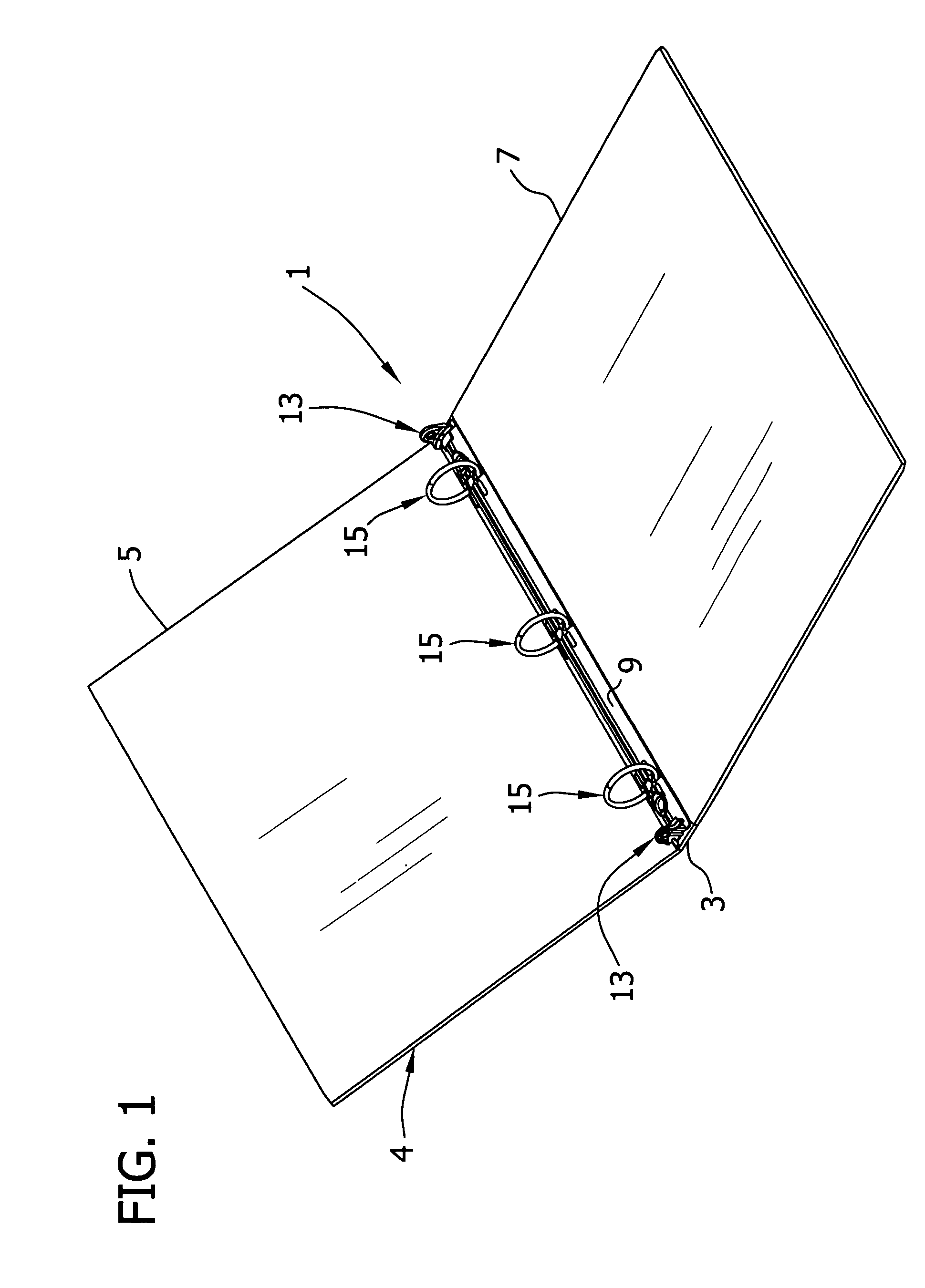
[0027] Referring now to the drawings, and particularly to FIG. 1, a ring binder mechanism according to the present invention is designated generally by reference numeral 1. The mechanism 1 is shown mounted on a spine 3 of a notebook 4 having a front cover5 and a back cover 7 hingedly attached to the spine. The front and back covers 5, 7 are movable to selectively cover or expose pages (not shown) retained by the mechanism 1. Ring binder mechanisms mounted on surfaces other than a notebook, however, do not depart from the scope of the present invention.

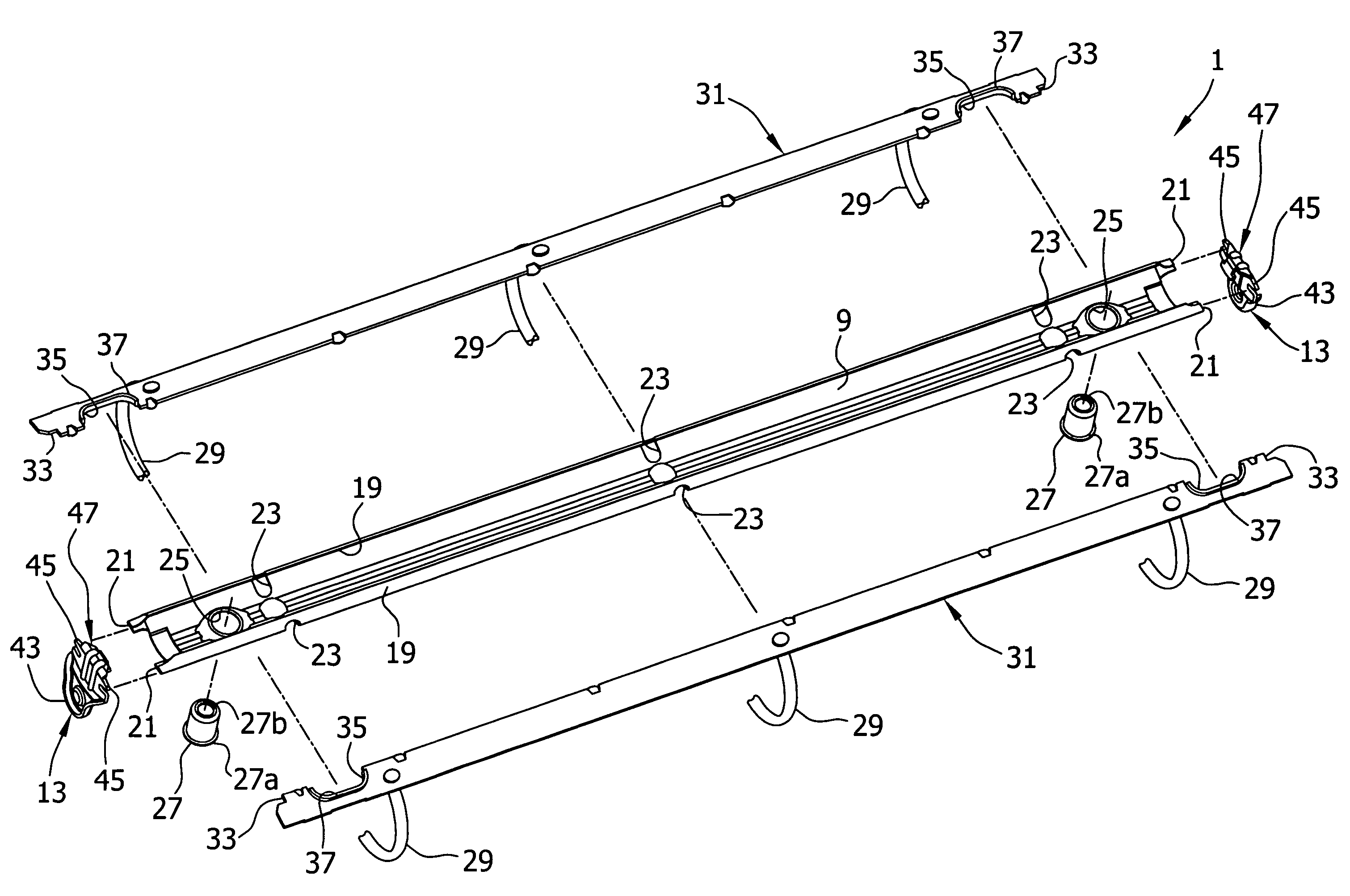
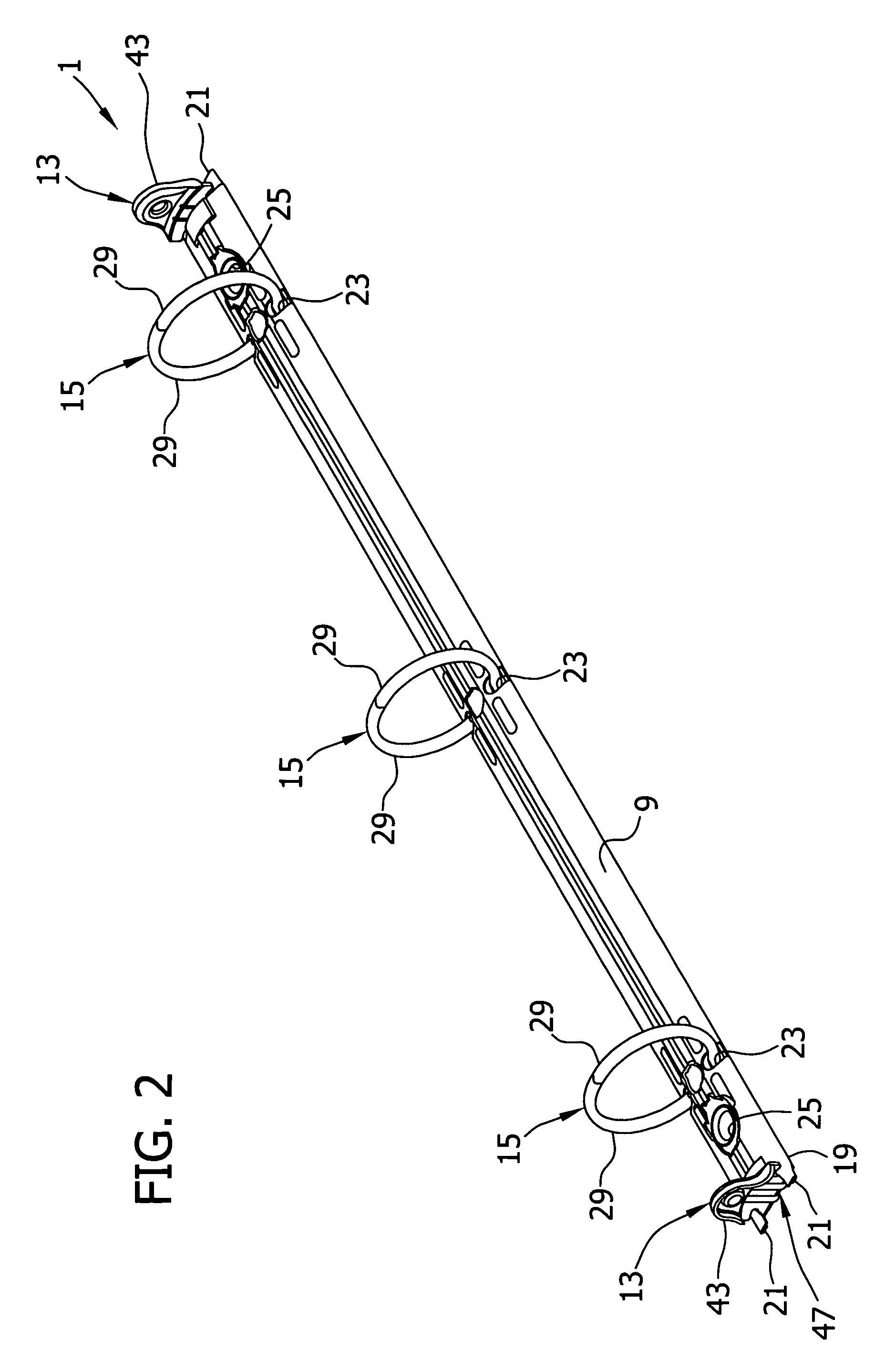
[0028] As shown in FIGS. 1 and 2, the ring binder mechanism 1 includes an elongate housing 9 that supports two substantially similar actuating levers (each desi...


PUM


Abstract

A ring binder mechanism for retaining loose-leaf pages comprises an elongate housing that supports two hinge plates for loose pivoting motion. Ring members attach to the hinge plates and move with the pivoting motion of the hinge plates between a closed position and an open position. Levers are pivotally attached to longitudinal ends of the housing for pivoting the hinge plates to move the ring members. The hinge plates define an opening therein, generally adjacent to one of the levers, for receiving a fastener through the hinge plates to attach the mechanism to a cover. Reinforcing structure is provided around the opening for rigidifying the hinge plates in that area and for preventing the hinge plates from bending or deforming near the opening during operation.

Description

BACKGROUND OF THE INVENTION [0001] This invention relates to a ring binder mechanism for retaining loose-leaf pages, and in particular to an improved mechanism having hinge plates that are reinforced. [0002] As is known in the art, a typical ring binder mechanism retains loose-leaf pages, such as hole-punched papers, in a file or notebook. It generally features multiple rings, each including two half ring members that mount on two adjacent hinge plates. The hinge plates join together about a pivot axis and loosely pivot within an elongate housing, allowing the ring members mounted thereon to move between an open position where papers may be added or removed and a closed position where papers are retained and can move along the rings. An operator may typically open or close the ring members by manually pulling the ring members apart or pushing them together. In addition, in some mechanisms the operator can move levers located at ends of the housing to open or close the ring members. ...

Claims


Application Information

Patent Timeline
IPC IPC(8): B42F13/02
CPCB42F13/26B42F13/0066
Inventor NG, WING YIU
Owner WORLD WIDE STATIONARY MFG CO LTD
Learn More