Display device and method for controlling a grating thereof

Active Publication Date: 2017-02-09
BOE TECH GRP CO LTD +1
View PDF7 Cites 5 Cited by
  • Summary
  • Abstract
  • Description
  • Claims
  • Application Information

AI Technical Summary

Benefits of technology

[0037]In the display device and the method for controlling a grating thereof the present invention, a grating corresponding to the arrangement of pixels is adopted, so that the electrodes of the grating substrate have an increased width, requirements for accuracy of the process for fabricating the electrodes are reduced, the process is simplified, the co

Problems solved by technology

Therefore, high accuracy is required for the width of electrodes, the process is difficult, and crosstalk tends to occur.
The electrodes of the grating substrate are controlled in such a row-by-row and one-by-one ma

Method used


Image

  • Display device and method for controlling a grating thereof
  • Display device and method for controlling a grating thereof
  • Display device and method for controlling a grating thereof

Examples


embodiment 1

[0045]As shown in FIGS. 1-5, the present embodiment provides a display device, which at least comprises a pixel array and a grating.

[0046]The pixel array comprises a plurality of rows of pixels, and each pixel comprises at least one sub-pixel.

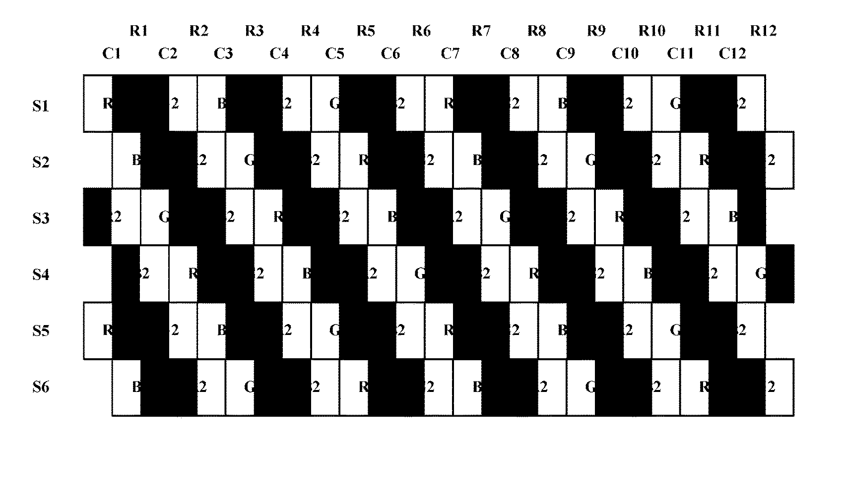
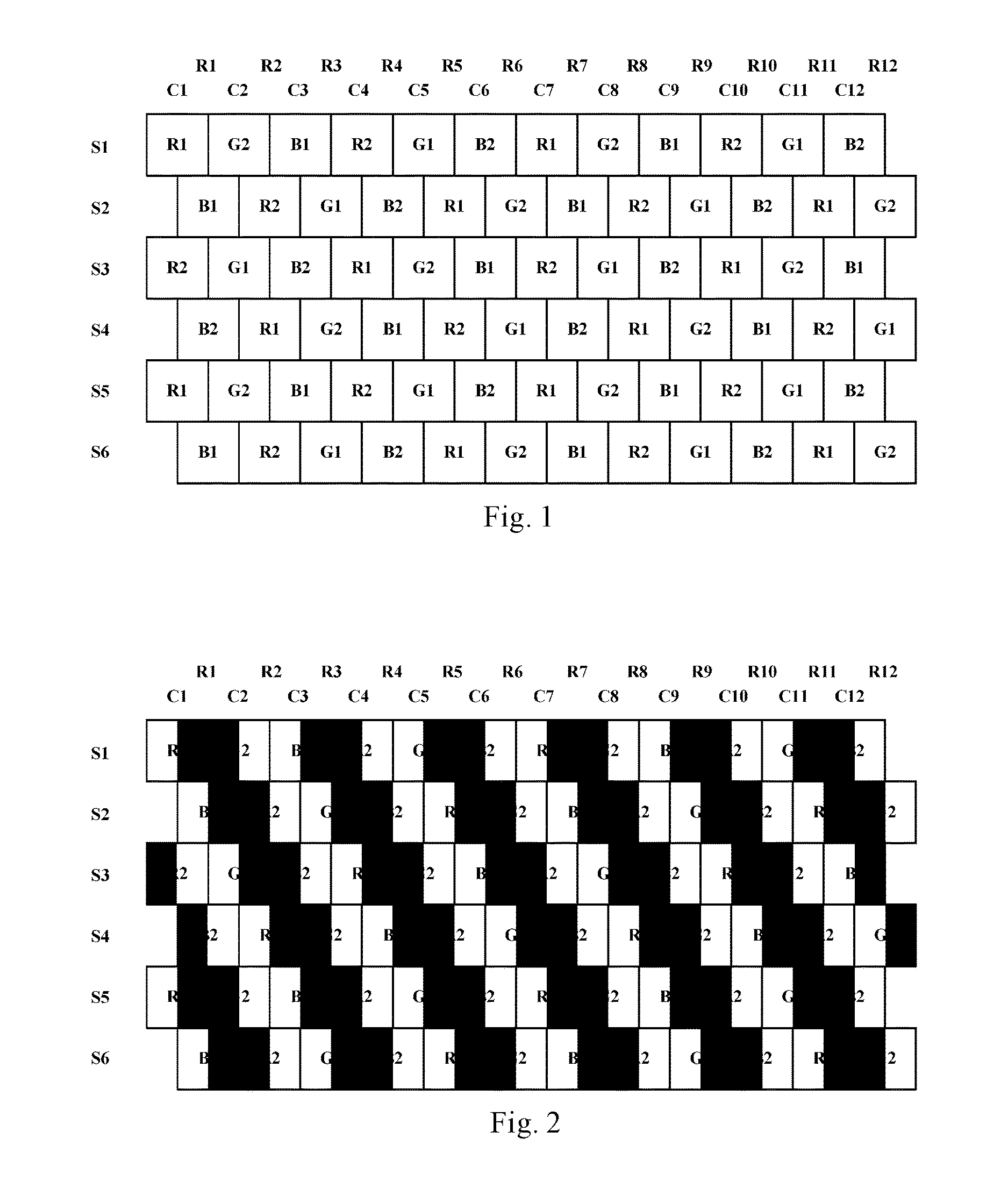
[0047]Each row of sub-pixels is formed by sub-pixels of at least three colors which are arranged in a cyclic manner, each row of sub-pixels comprises sub-pixels of a same number, and each sub-pixel has a same size.

[0048]The sub-pixels of each odd-numbered row are aligned with respect to their left edges, sub-pixels of each even-numbered row are aligned with respect to their right edges, and an odd-numbered row of sub-pixels and an even-numbered row of sub-pixels are offset in a longitudinal direction by a preset length which is smaller than a longitudinal length of a sub-pixel.

[0049]Any neighboring sub-pixel has a different color.

[0050]The grating comprises a liquid crystal layer as well as a first substrate and a second substrate at two sides ...

embodiment 2

[0103]FIG. 6 is a schematic flow chart for illustrating a grating controlling method in embodiment 2 of the present invention.

[0104]In the present embodiment, a method for controlling a grating of a display device comprises: turning on the grating by applying a same level signal to the electrodes of the second substrate and applying a high level signal or a low level signal alternately to the electrodes of the first substrate; and by applying a same level signal to the electrodes of the first substrate and the second substrate, turn off the grating.

[0105]For example, the method can comprise: turning on the grating by applying a high level signal to the electrodes of the second substrate and applying a high level signal and a low level signal alternately to the electrodes of the first substrate. The method can comprise: turning on the grating by applying a low level signal to the electrodes of the second substrate and applying a high level signal and a low level signal alternately to...


PUM


Abstract

The present invention provides a display device and a method for controlling a grating thereof, and belongs to the field of display technology, and can overcome the problem in which electrodes of the grating substrate require high fabricating accuracy and are difficult to fabricate due to the arrangement of a pixel array. The display device at least comprises a pixel array and a grating, an odd-numbered row of sub-pixels and a neighboring even-numbered row of sub-pixels are offset in a longitudinal direction by a preset length, a first substrate of the grating comprises a plurality of electrodes, each electrode comprises a plurality of segments which are continuous and are offset in a segment-wise manner by a predefined length from an end to the other end of the electrodes. Since the pixels and the grating are arranged in a corresponding manner, the electrodes of the grating substrate have an increased width, requirements for accuracy of the process for fabricating the electrodes are reduced, and the fabrication difficulty is reduced. By turning on and off the grating, a switch of the display device between 2D and 3D display can be realized. (FIG. 3)

Description

RELATED APPLICATIONS[0001]The present application is the U.S. national phase entry of PCT / CN2015 / 084280 with an International filing date of Jul. 17, 2015, which claims the benefit of Chinese Application No. 201510102610.7, filed Mar. 9, 2015, the entire disclosures of which are incorporated herein by reference.FIELD OF THE INVENTION[0002]The present invention relates to the field of display technology, and particularly to a display device and a method for controlling a grating thereof.BACKGROUND OF THE INVENTION[0003]The principle for 3D display technology lies in that a left eye and a right eye of a viewer are made to receive different images, the left and right images are analyzed and overlapped by the brain, so that a layering effect of the image is perceived by the viewer and a stereoscopic effect is thus generated.[0004]Currently, the 3D display device generally comprises two kinds, i.e., a display device which requires 3D glasses, and a naked-eye 3D display device. A parallax...

Claims


Application Information

Patent Timeline
IPC IPC(8): G02F1/1343G02F1/29G02F1/1335G02F1/133G02F1/137G02B27/22G02B30/31
CPCG02F1/134336G02F1/137G02B27/2214G02F1/133512G02F1/1368G02F1/13306G02F1/29G02F2201/52G02F2001/134345G02F1/13439G02F1/134309G02B30/31H04N13/356H04N13/31H04N13/317G02B30/27
Inventor LU, PENGCHENGGUO, RENWEICHEN, CHUNGCHUNDONG, XUE
Owner BOE TECH GRP CO LTD
Why Eureka
Try Eureka