Manufacturing productivity scoreboard

a manufacturing and productivity scoreboard technology, applied in the field of scoreboards, can solve the problems of repetitive and dull manufacturing jobs, long and difficult tasks, and create a significant burden in the job shop, and achieve the effect of saving information

a manufacturing and productivity scoreboard technology, applied in the field of scoreboards, can solve the problems of repetitive and dull manufacturing jobs, long and difficult tasks, and create a significant burden in the job shop, and achieve the effect of saving information

US20060010001A1Active Publication Date: 2006-01-12NORTH STAR MASCH LLC

Image

  • Manufacturing productivity scoreboard
  • Manufacturing productivity scoreboard
  • Manufacturing productivity scoreboard

Examples


Embodiment Construction

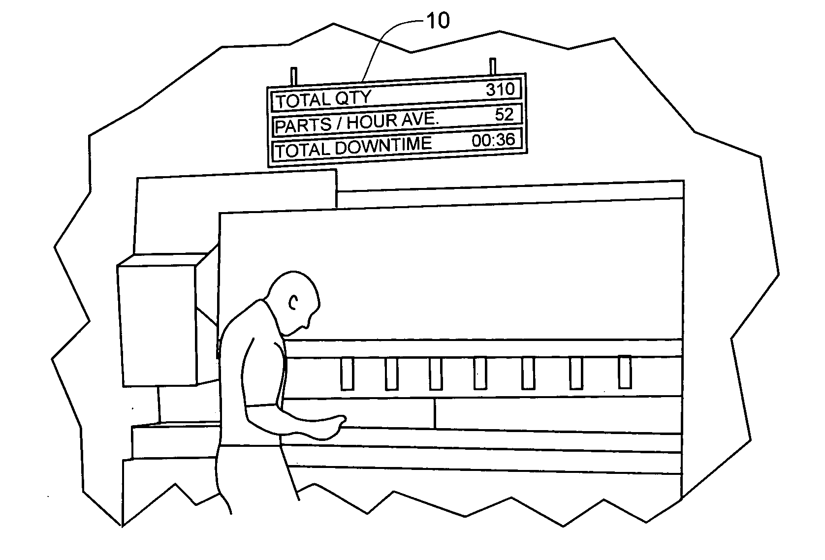
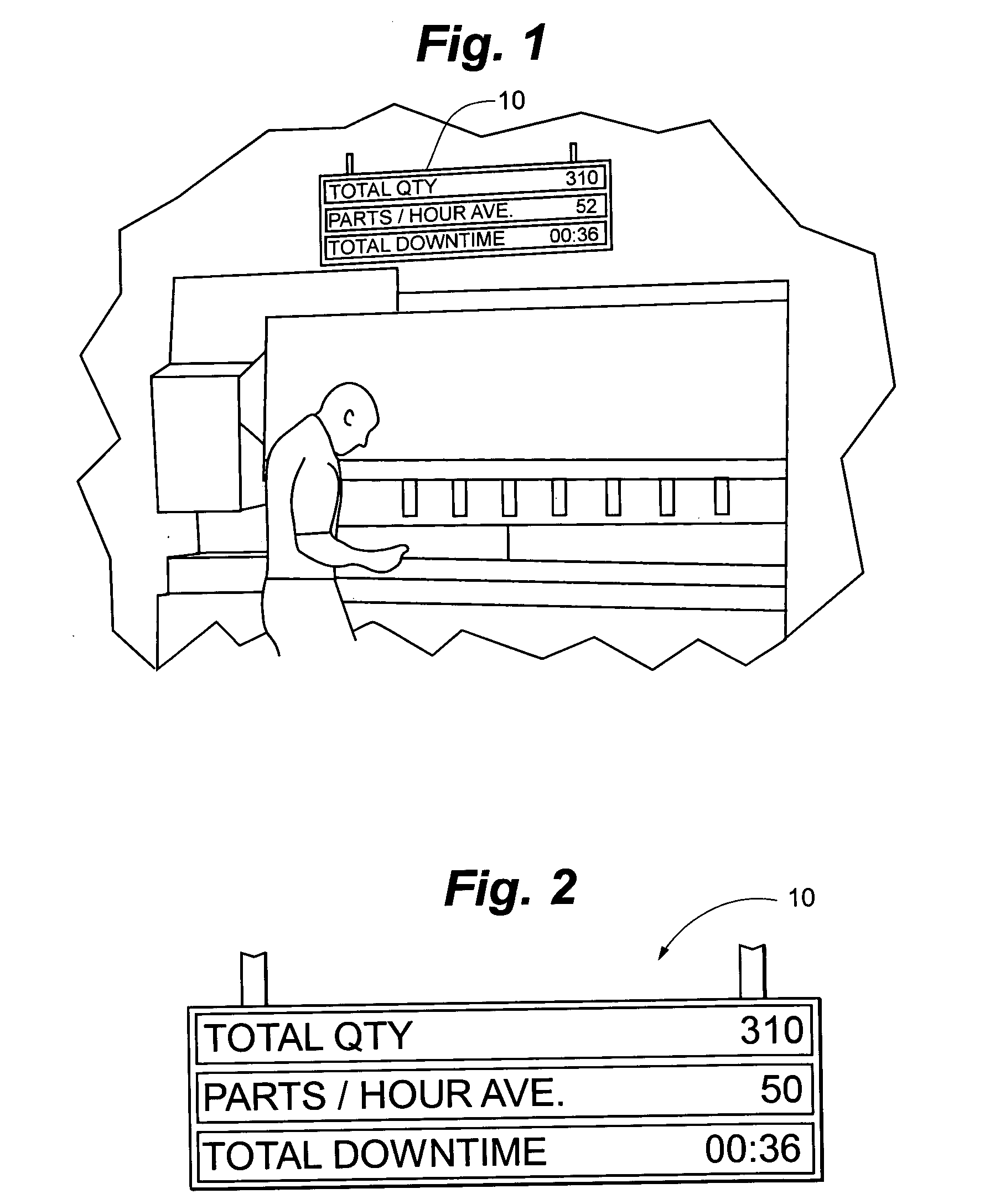
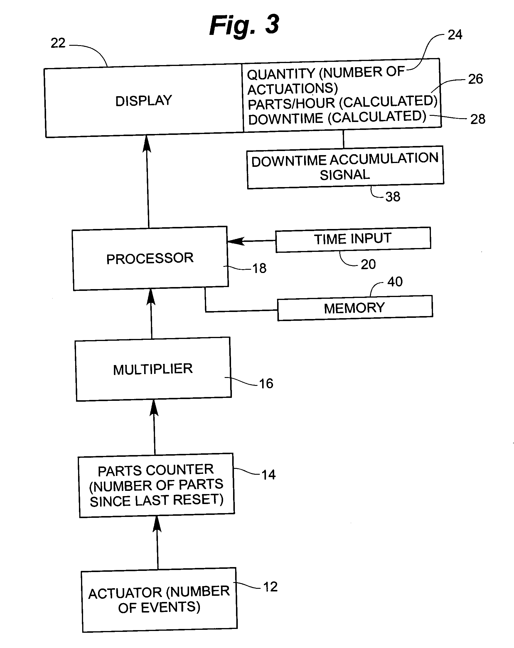
[0023] The manufacturing productivity scoreboard 10 generally includes actuator 12, parts counter 14, multiplier 16, processor 18, time input 20 and display 22. During a manufacturing process, multiple steps are performed. Typically, one or more of these steps is performed at a given workstation while others are performed at other workstations. The present invention monitors activities at a selected workstation. The actuator 12 will typically be a momentary contact switch that is in some form triggered when a part arrives or departs from a given workstation. Between a part's arrival and departure at a given workstation, any number of manufacturing events may occur. The actuator 12 in the present situation is actuated either at the beginning, during or at the end of this series of manufacturing events. The time that passes between a first actuation and a second actuation may be referred to as the cycle time. Cycle times are recorded continuously since the last time that the manufactu...


PUM


Abstract

A system for displaying manufacturing productivity information, including a controller connected to a display device, a momentary actuator and a display. The controller records a plurality of cycle times between sequential actuations of the actuator and stores the cycle times in a library. The controller maintains a count of actuations that have occurred since reset of the timer and records time passed since the reset. The controller determines a median value of the cycle times and multiplies the median value of cycle times by the count of actuations to obtain a resulting value and subtracts the resulting value from the total time since the last reset to determine a value for total downtime. The controller activates the display to show the value for total downtime.

Description

CLAIM TO PRIORITY [0001] This application claims priority to U.S. Provisional Application Ser. No. 60 / 586,352 filed Jul. 8, 2004 entitled “Manufacturing Productivity Scoreboard” which is incorporated herein in its entirety by reference.FIELD OF THE INVENTION [0002] The invention relates to scoreboards that are used in manufacturing facilities to prominently display productivity information. BACKGROUND [0003] In today's modern manufacturing environment there has been a shift towards the philosophy of lean manufacturing. In an effort to comply with this philosophy, manufacturing managers are constantly making efforts to reduce waste and to promote better productivity among their workers. One tool that has been utilized in an effort to improve productivity is for the manufacturing facility to prominently display scoreboards within the facility in an effort to encourage teamwork and a spirit of competitive improvement among the workers. [0004] For example, in an effort to increase produ...

Claims


Application Information

Patent Timeline
12 Jan 2006
Publication
US20060010001A1
IPC
G06Q99/00
CPC
G06Q10/0639; G06Q10/06
Inventors
HAMELINK, JEFF