Automatic toilet flushing system and method

a flushing system and automatic technology, applied in the field of toilets, can solve the problems of complex and costly automatic flushing systems used in commercial or industrial settings, inability to use in private residences, and inability to achieve true reduction of the cost associated with applying, etc., to achieve simple and easy conversion and low cost

Active Publication Date: 2006-01-19
SDB IP HLDG
View PDF18 Cites 25 Cited by
  • Summary
  • Abstract
  • Description
  • Claims
  • Application Information

AI Technical Summary

Benefits of technology

[0027] In accordance with the foregoing method, a conventional bowl-type toilet may simply and easily be converted into an automatic flush toilet at relatively low cost and without the necessity of purchasing a new toilet with an automatic toilet flushing system. In operation, when a person, animal, or object approaches the automatic flush toilet, the person, animal, or object will interrupt and ref

Problems solved by technology

Typically, such automatic flushing systems used in commercial and industrial settings are complex and costly.
Accordingly, automatic flushing systems intended for use in commercial or industrial settings are not typically amenable to use in private residences.
The attempts made so far in the art have not truly reduced the costs associated with applying an automatic flushing system to a bowl-type toilet.
Additionally, some of the r

Method used


Image

  • Automatic toilet flushing system and method
  • Automatic toilet flushing system and method
  • Automatic toilet flushing system and method

Examples


Embodiment Construction

[0045] For purposes of the description hereinafter, the terms “upper”, “lower”, “right”, “left”, “vertical”, “horizontal”, “top”, “bottom”, and derivatives thereof, shall relate to the invention as it is oriented in the drawing figures. However, it is to be understood that the invention may assume various alternative variations and step sequences except where expressly specified to the contrary. It is also to be understood that the specific devices and processes illustrated in the attached drawings and described in the following text are simply exemplary embodiments of the invention. Hence, specific dimensions and other physical characteristics related to the embodiments disclosed hereinafter are not to be considered limiting.

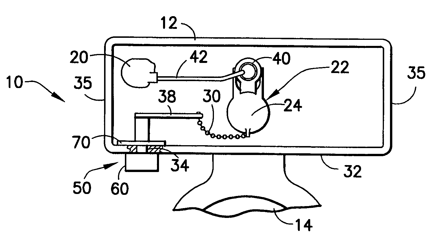
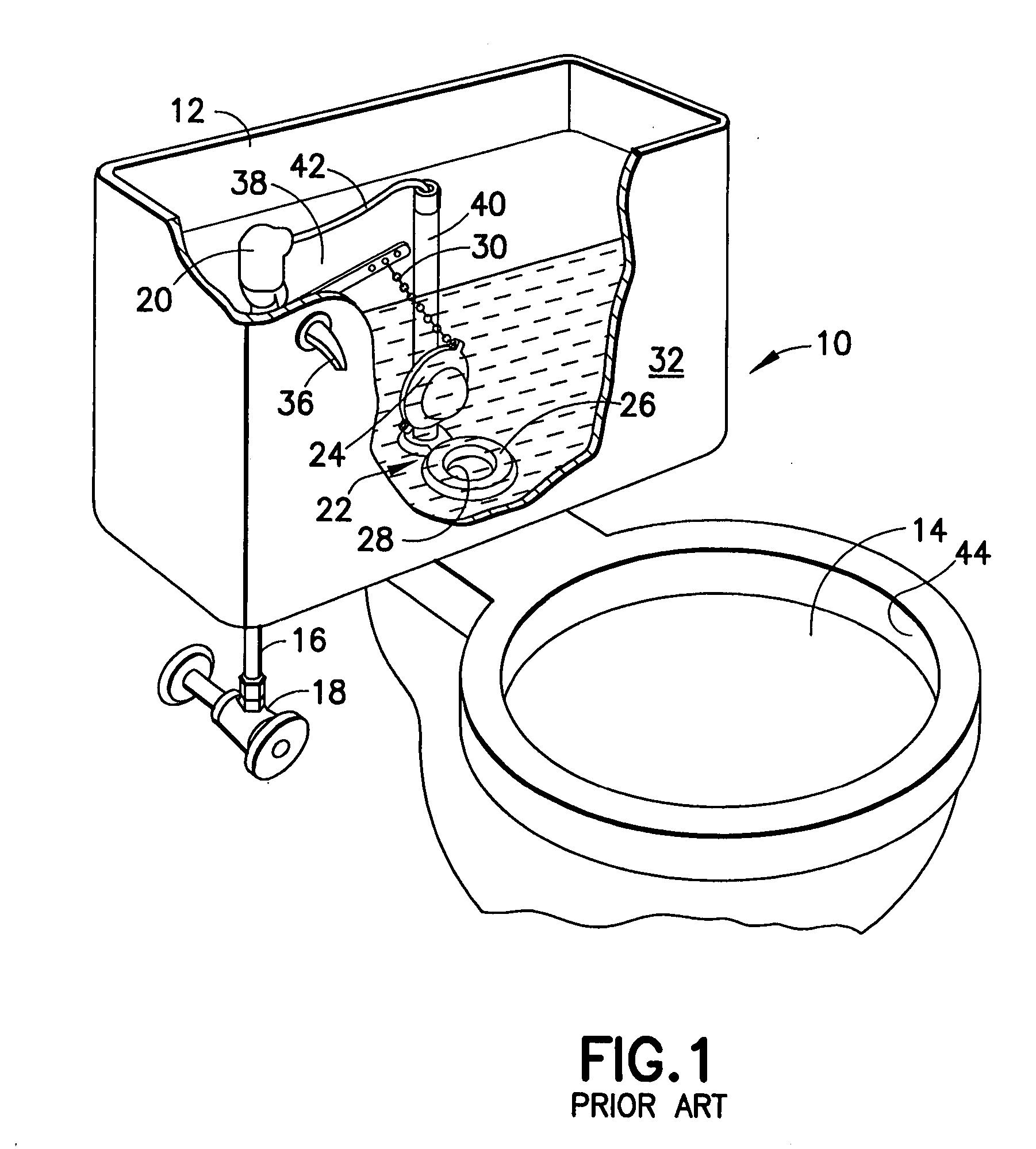
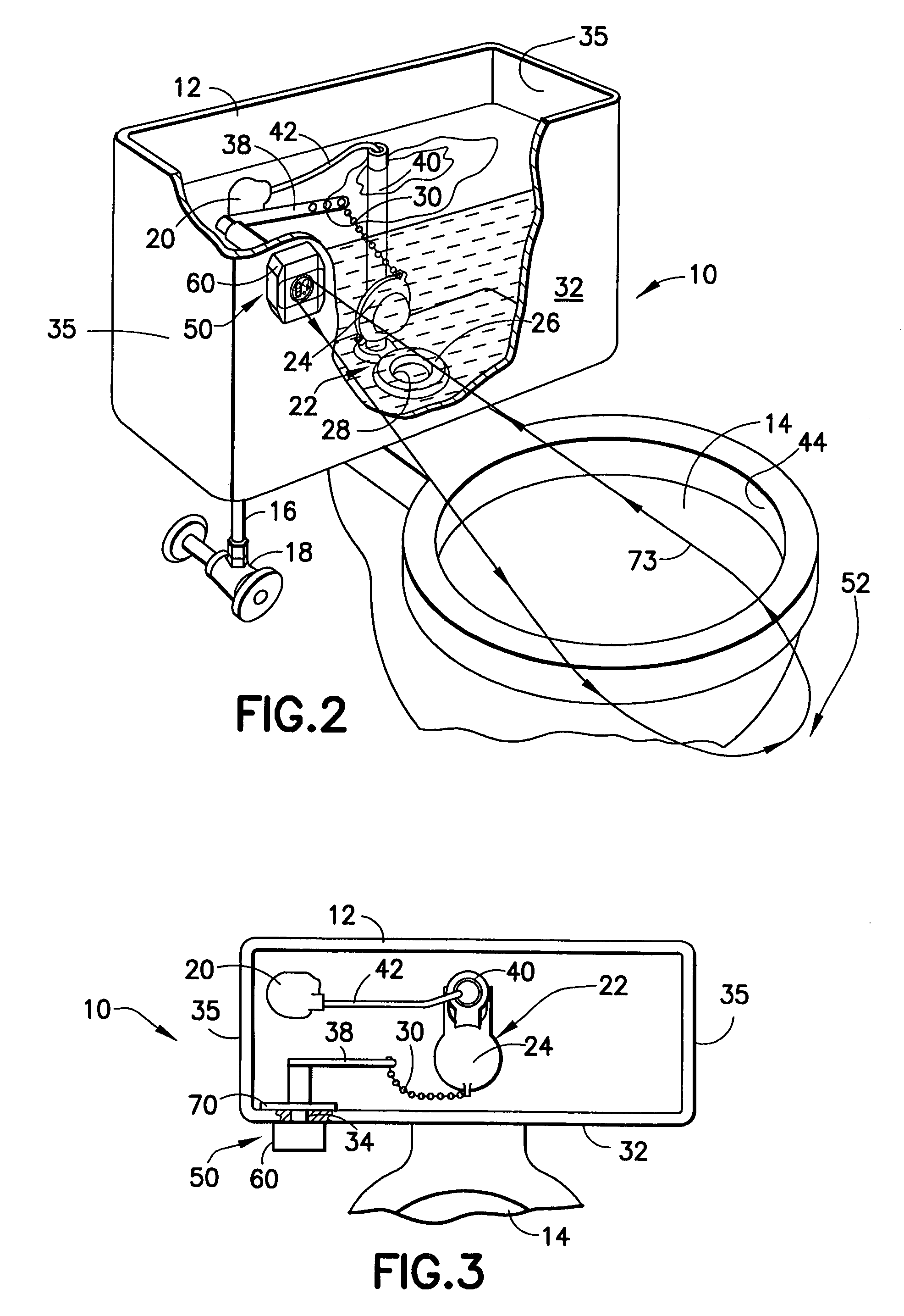
[0046] Referring to FIG. 1, a conventional bowl-type toilet 10 that may be retrofitted to an automatic flush toilet in accordance with the present invention is shown. The toilet 10 includes a water holding tank 12 (hereinafter “holding tank 12”) connected to a...


PUM


Abstract

A toilet (10) having an automatic flush assembly (50) includes a toilet bowl (14), a water holding tank (12) for supplying water to the toilet bowl (14), and a flush valve (22). The holding tank (12) supplies water to the toilet bowl (14) and defines a handle opening (34) for an actuating handle (36) of the toilet (10). The flush valve (22) provides fluid communication between the toilet bowl (14) and the holding tank (12). The automatic flush assembly (50) is mounted in the handle opening (34) and includes a sensor section (54), a control section (56), and an actuating mechanism (58). The sensor section (56) detects the presence of a person in front of the toilet bowl (14). The control section (56) receives a detection signal from the sensor section (54) and initiates a flush signal to the actuating mechanism (58), which actuates the flush valve (22).

Description

BACKGROUND OF THE INVENTION [0001] 1. Field of the Invention [0002] The present invention relates to toilets and, more particularly, to automatic flush toilets adapted for use in private residences. Further, the present invention relates to automatic flushing systems and assemblies for retrofitting bowl-type toilets typically found in private residences. [0003] 2. Description of Related Art [0004] Automatic flushing systems are now well-known and widely used in commercial and industrial settings. Typically, an automated flushing system will cause the automatic flushing of a toilet or urinal after a user leaves the immediate proximity of the toilet or urinal. These types of devices are now commonly found in hotels, airports, sport stadiums, and other similar public facilities. [0005] Most commercially available automatic flushing systems are designed for use with diaphragm-type flush valves that incorporate a diaphragm made of molded rubber, which effectuates water flow from a water ...

Claims


Application Information

Patent Timeline
IPC IPC(8): A47K13/00E03D5/10
CPCE03D5/105
Inventor BUSH, SHAWN D.
Owner SDB IP HLDG
Why Eureka
Try Eureka