Electric power control device for watercraft

a control device and watercraft technology, applied in the direction of propulsive elements, marine propulsion, vessel construction, etc., can solve the problems of insufficient power provided by the fuel cell system, hinder etc., and achieve the effect of hindering the expansion and diversification of the watercraft system

Inactive Publication Date: 2006-01-19
YAMAHA MARINE KK
View PDF8 Cites 10 Cited by
  • Summary
  • Abstract
  • Description
  • Claims
  • Application Information

AI Technical Summary

Benefits of technology

[0006] In the field of relatively small watercraft, the hulls, propulsion units such as outboard motors or inboard/outboard stem drives, and a plurality of other devices, each of which may come from different manufacturers, are combined to form the complete watercraft. When fuel cells are used as a power source in a relatively small watercraft, the expandability and diversification of the watercraft system is hindered, because the power provided by the fuel cell system may become insufficient when additional auxiliary and electric appliances are added, or if a twin installation of outboard motors is employed.
[0007] Thus, in accordance with an embodiment, an electric power control device for a watercraft is provided. The power control device can comprise at least first and second fuel cells configured to generate electric power, a plurality of loading devices driven by the electric power supplied by the multiple fuel cells, and a control device configured to operate the fuel cells in response to an electric power load generated by the loading devices. The control device can comprise an efficiency characteristics recognition device configured to recognize the respective efficiency characteristics for each of the first and second fuel cells. The control device can also comprise an electric power requirement recognition device configured to recognize the electric power required by the loading devices. Further, the control device can also co...

Problems solved by technology

When fuel cells are used as a power source in a relatively small watercraft, the expandability and diversification of the watercraft system is hindered, because the power...

Method used


Image

  • Electric power control device for watercraft
  • Electric power control device for watercraft
  • Electric power control device for watercraft

Examples


Embodiment Construction

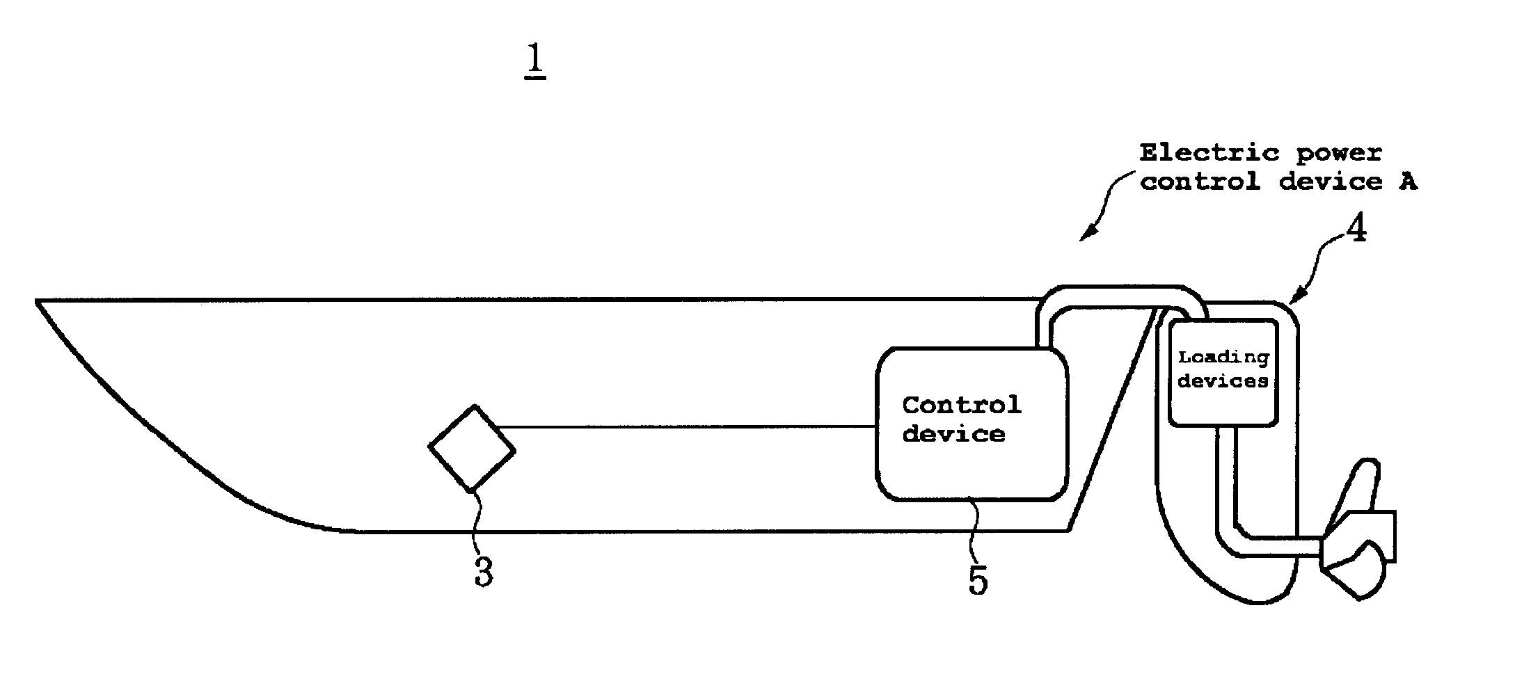
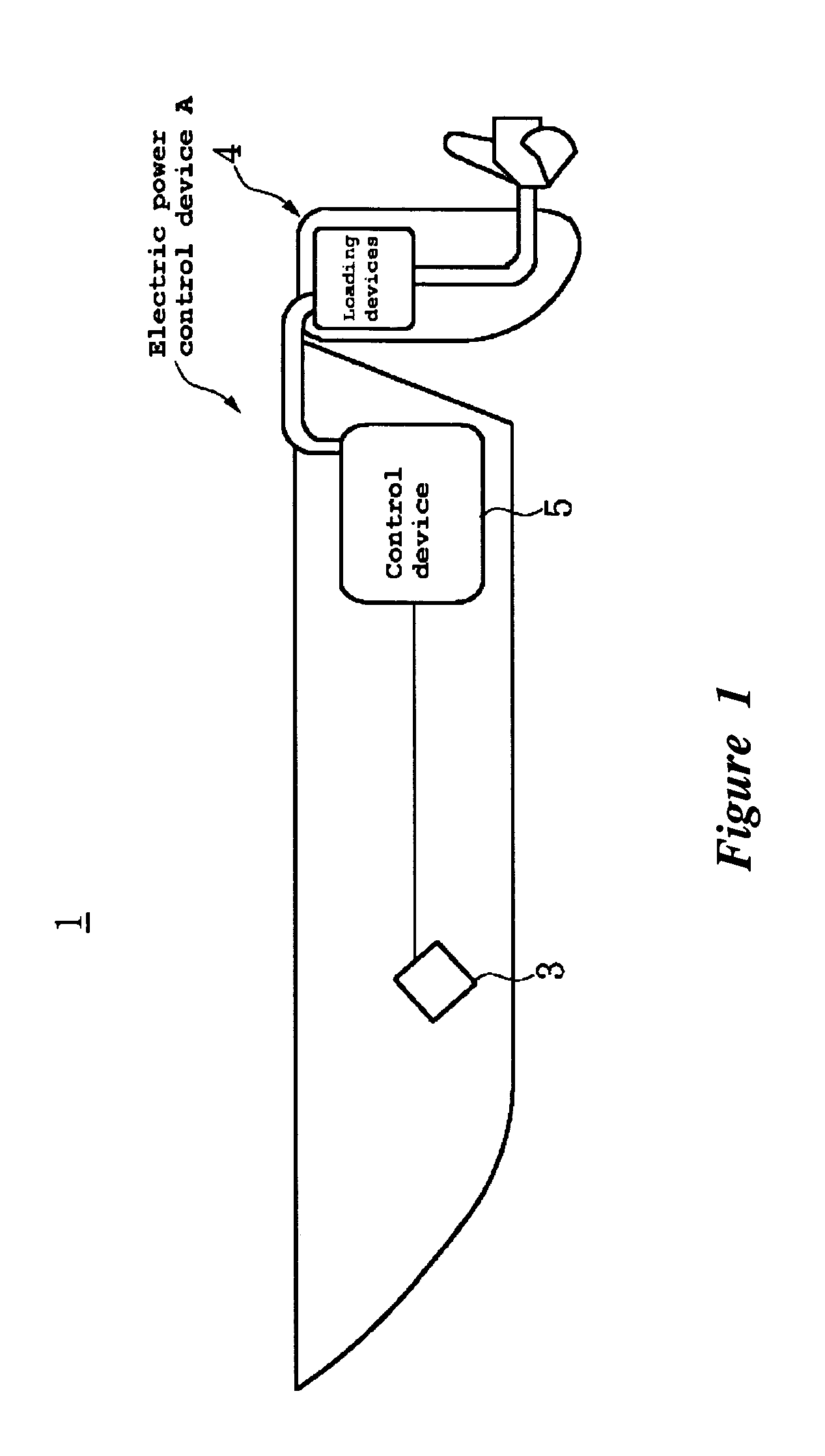
[0013]FIG. 1(a) is a side elevational view of a small watercraft 1 having a controller in accordance with an embodiment. The embodiments disclosed herein are described in the context of a small watercraft because the embodiments disclosed herein have particular utility in this context. However, the embodiments and inventions herein can also be applied to other boats having other types of propulsion units as well as other types of vehicles.

[0014] As used herein, the terms “front,”“rear,”“left,”“right,”“up” and “down,” correspond to the direction assumed by a driver of the watercraft.

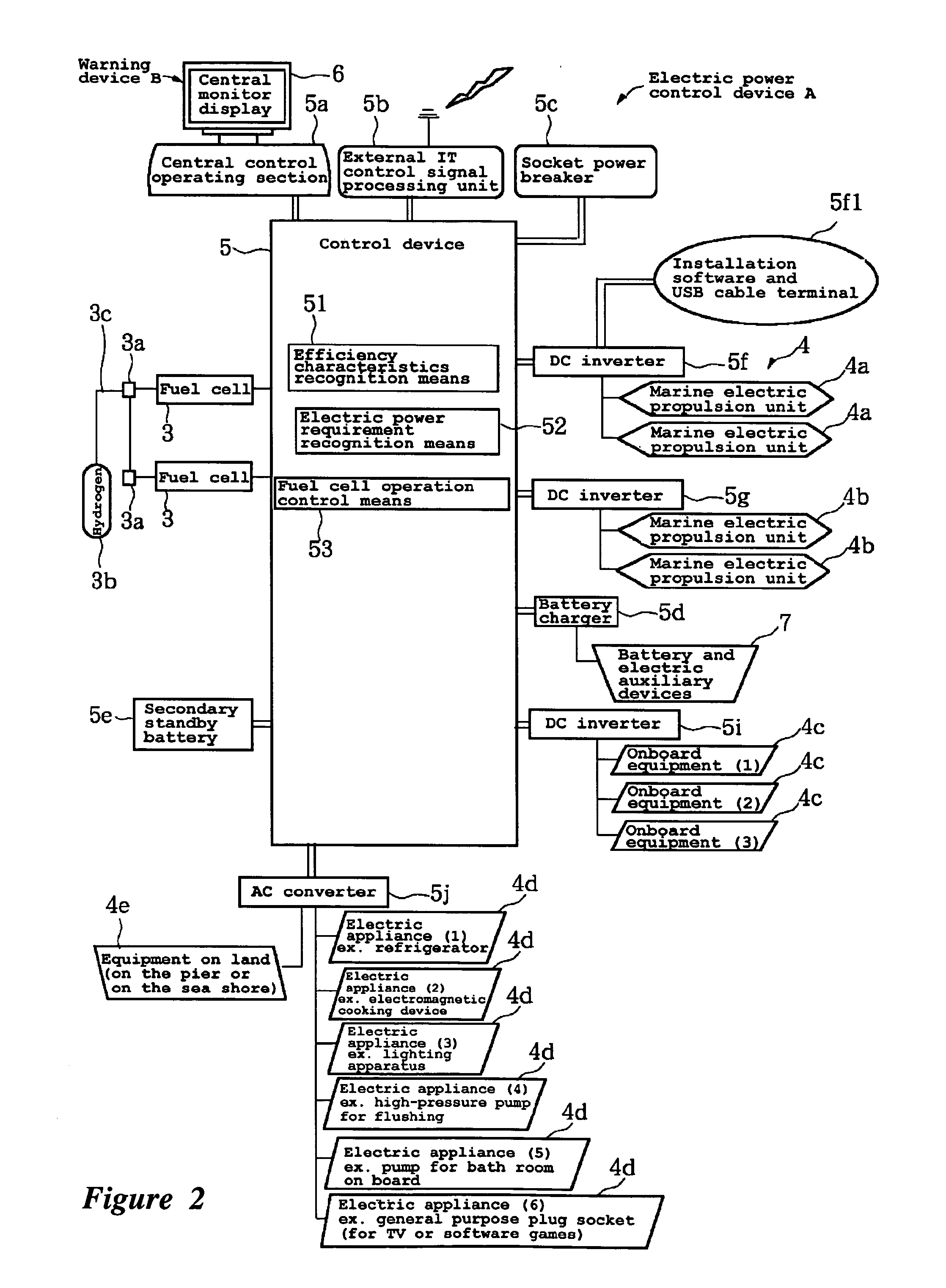
[0015] The watercraft 1, in some embodiments, is equipped with an electric power control device A. The electric power control device A can have multiple fuel cells 3, loading devices 4 driven by the electric power supplied by the multiple fuel cells 3, and a control device 5 for operating the fuel cells 3 in response to the electric power load required by the loading devices 4.

[0016] The structure of t...


PUM


Abstract

An electric power control device can have multiple fuel cells, loading devices driven by the electric power supplied by the multiple fuel cells, and a control device for operating the fuel cells in response to the electric power load required by the loading devices. The control device can have an efficiency characteristics recognition device for recognizing the efficiency characteristics for each of the multiple fuel cells, an electric power requirement recognition device for recognizing the electric power required by the loading devices, and a fuel cell operation control device for controlling the operation of the fuel cells so that the efficiency characteristics get closer to the maximum efficiency loading point in response to the recognized electric power requirement.

Description

PRIORITY INFORMATION [0001] This application is based on and claims priority under 35 U.S.C. § 119 to Japanese Patent Application No. 2004-206801, filed on Jul. 14, 2004, the entire contents of which is hereby expressly incorporated by reference.BACKGROUND OF THE INVENTIONS [0002] 1. Field of the Inventions [0003] The present inventions relate to control devices for relatively small watercraft such as motorboats, pontoon boats, house boats, and other types of watercraft. More specifically, the present inventions relate to an electric power control device for supplying the electric power to loading devices by means of multiple fuel cells. [0004] 2. Description of the Related Art [0005] Conventionally, fuel cells are known to be applied to automobiles, domestic electric appliances, mobile equipment and others as an electric power supply device. Fuel cells also frequently appear in various periodicals including magazines. However, such fuel cells are generally utilized within a particu...

Claims


Application Information

Patent Timeline
IPC IPC(8): B60L1/00
CPCB60L11/1887B60L11/1894B63H21/17B63H21/21B63H2020/003B60L2200/32Y02T70/5209Y02T90/34Y02T90/38Y02T90/46B63H2021/003B60L58/40B60L58/34Y02T70/50Y02T90/40Y02T10/70B63H20/007
Inventor MATSUSHITA, YUKIOKAWAI, TAKAOKOBAYASHI, NOBORU
Owner YAMAHA MARINE KK
Why Eureka
Try Eureka