Matched filter

A matched filter and selector technology, applied in electrical components, multiplex communication, transmission systems, etc., can solve problems such as unrealizable layout

Inactive Publication Date: 2003-10-15
FUJITSU LTD
View PDF0 Cites 0 Cited by
  • Summary
  • Abstract
  • Description
  • Claims
  • Application Information

AI Technical Summary

Problems solved by technology

For this reason, the circuit is excessively concentrated from the point of view of circuit structure or layout, making this layout impossible

Method used


Image

  • Matched filter
  • Matched filter
  • Matched filter

Examples


Embodiment Construction

[0071] Hereinafter, various embodiments of the present invention will be described with reference to the accompanying drawings.

[0072] (A) Description of one embodiment of the present invention

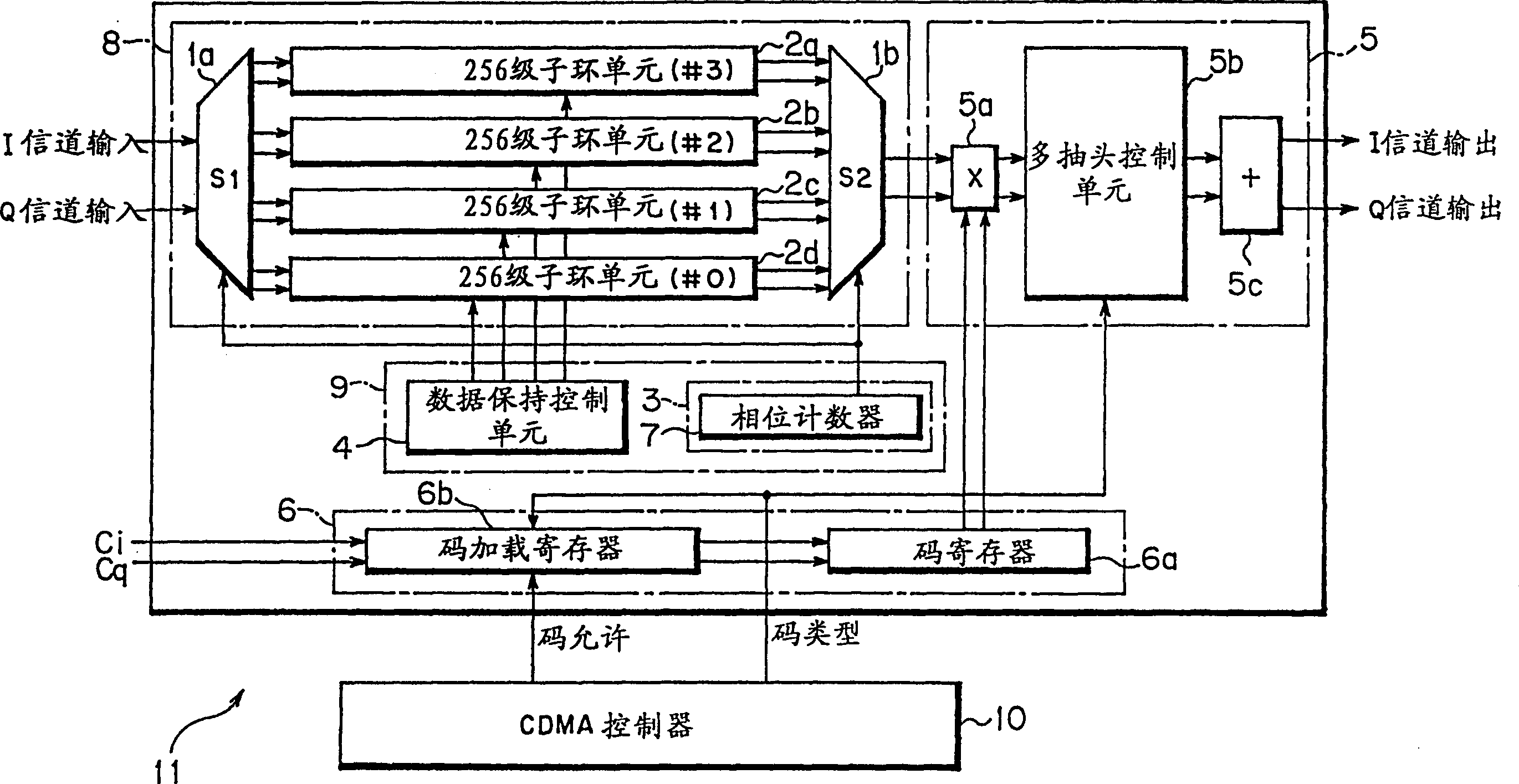
[0073] figure 1 is a block diagram of the matched filter used in the present invention. Such as figure 1 The matched filter shown includes a CDMA controller 10 , a spread spectrum data path unit 8 , a spread spectrum data path input control unit 9 , a spread spectrum code setting unit 6 and a calculation unit 5 .

[0074] For the sake of convenience of the description hereinafter, specific numerical values ​​used in the matched filter 11 to which the present invention is applied are listed below. The number of taps is T=256, corresponding to the length of the spreading code used. The number O of oversampling is the number of oversampling performed in one chip duration, and O=4 is set. The bit number D of the spread spectrum data path represents the bit number equal to the dat...


PUM


Abstract

In a matched filter, a spread data path unit holds inputted spread data, a multiplier unit multiplies an output of the spread data path unit by a spreading replica code, and an adder unit adds results of the multiplication and outputs an added result. The spread data path unit comprises a first selector being able to selectively output the spread data, a plurality of sub spread data path units each having a plurality of latch circuits temporarily holding the spread data from the first selector, and a second selector being able to selectively output outputs from the sub spread data path units, whereby a circuit scale of the spread data path unit is decreased.

Description

technical field [0001] The present invention relates to a matched filter in a wireless receiver suitable for direct sequence code division multiple access. Background technique [0002] In Direct Sequence Code Division Multiple Access (DC-CDMA [Direct Sequence Code Division Multiple Access]), the transmitter modulates the data code mainly by, for example, QPSK (Quadrature Phase Shift Keying), spreads its bandwidth with a spreading code and transmits the data code. On the other hand, the receiver performs cross-correlation using the same spreading code as in the transmitter, detects the peak of the correlation value, performs acquisition and tracking, and performs demodulation using correlation detection. [0003] Fig. 11(a) is a transmission unit of a wireless terminal in a CD-CDMA system using QPSK. In the transmitting unit of the DC-CDMA wireless terminal shown in Figure 11 (a), the data code is carried out QPSK modulation in the main modulation unit 30a, and the bandwid...

Claims


Application Information

Patent Timeline
Patent Type & Authority Patents(China)
IPC IPC(8): H03H17/02H04B1/707H04B1/7093
CPCH04B1/7093H04B2201/70707
Inventor 陈奔内岛诚
Owner FUJITSU LTD
Why Eureka
Try Eureka