Color display device and driving method thereof

a technology of color display and driving method, which is applied in the direction of electric digital data processing, instruments, computing, etc., can solve the problems of color balance destruction not only at the edge portion but also in the entire image, and achieve the effect of reducing inconformity

Inactive Publication Date: 2006-01-19
CANON KK
View PDF6 Cites 30 Cited by
  • Summary
  • Abstract
  • Description
  • Claims
  • Application Information

AI Technical Summary

Benefits of technology

[0031] As in the present invention, when image switching is performed by dividing a pixel into a first subpixel and a second subpixel provided with a color filter of any one species of red, green and blue and performing modulation of a hue change range at the first subpixel, a predetermined amount obtained from applied voltages before and after switching at the first subpixel is outputted by being superposed on a modulation amount with respect to the second subpixel in a predetermined period of time, so that it is possible to alleviate inconformity at the time of motion picture display.

Problems solved by technology

Further, when such a display color different in systematic color is observed, coloring is observed at an edge portion of a moving body in the motion picture display to result in inconformity with respect to the motion picture display.
Accordingly, in the case where an image effecting natural picture display by dithering is displayed as motion picture, the change becomes a cause of destruction of color balance not only at the edge portion but also in the entire image.

Method used


Image

  • Color display device and driving method thereof
  • Color display device and driving method thereof
  • Color display device and driving method thereof

Examples


embodiment 1

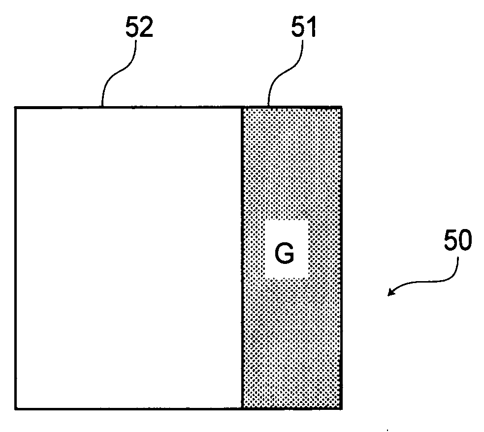
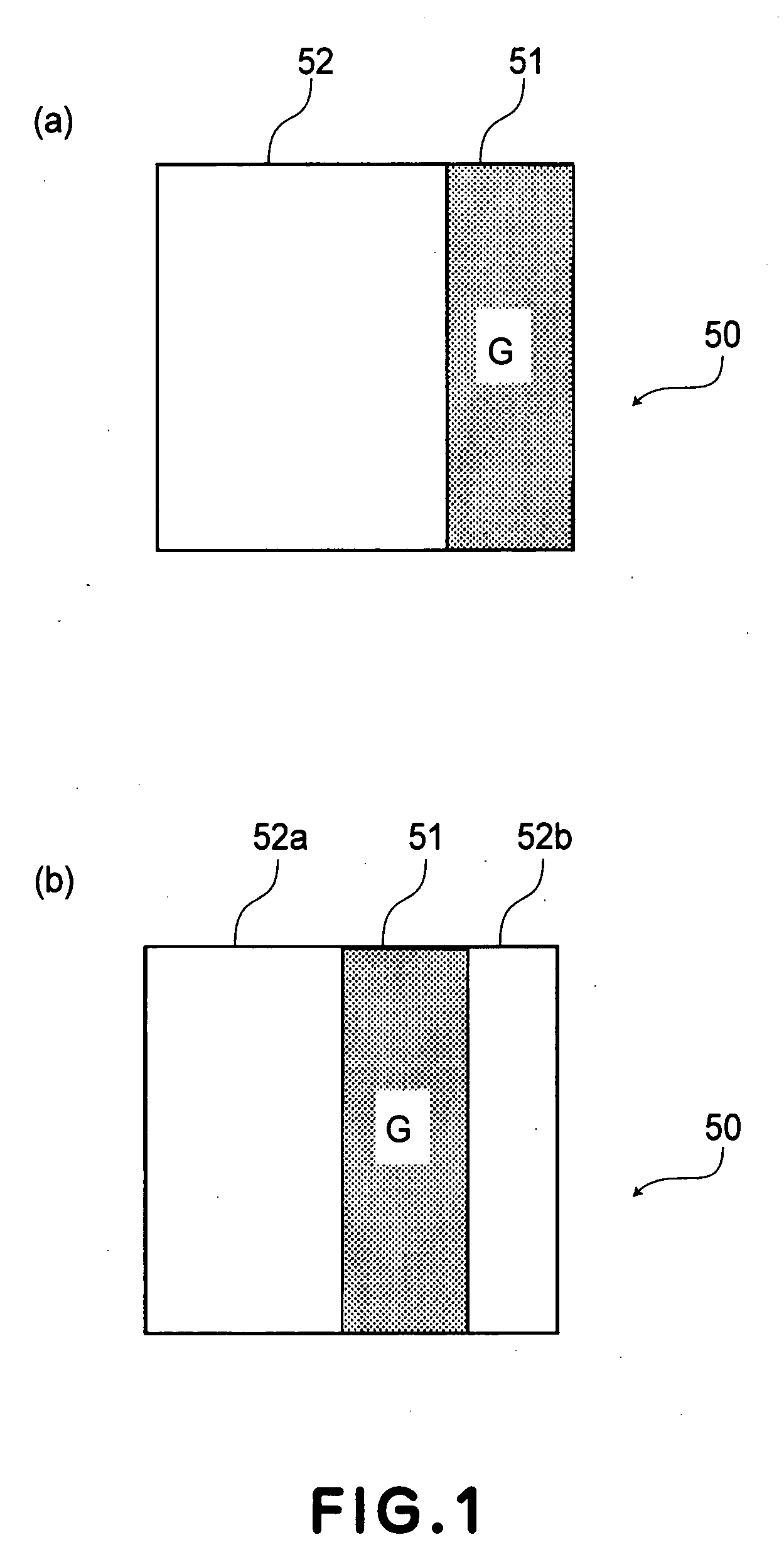
[0125] A pixel constitution of a liquid crystal display device used in Embodiment 1 is given, as shown in FIG. 12, by dividing one unit pixel into two subpixels and providing a green color filter to only a second subpixel 51 which is one of the subpixels. Incidentally, the liquid crystal display device includes unit pixels of 1200 in columns and 600 in row, and the cell thickness of this device 5 microns.

[0126] Further, at a unit pixel, an amount of retardation at the time of applying a voltage of ±5 V to a first subpixel 52 being a transparent subpixel provided with no color filter is about 300 nm.

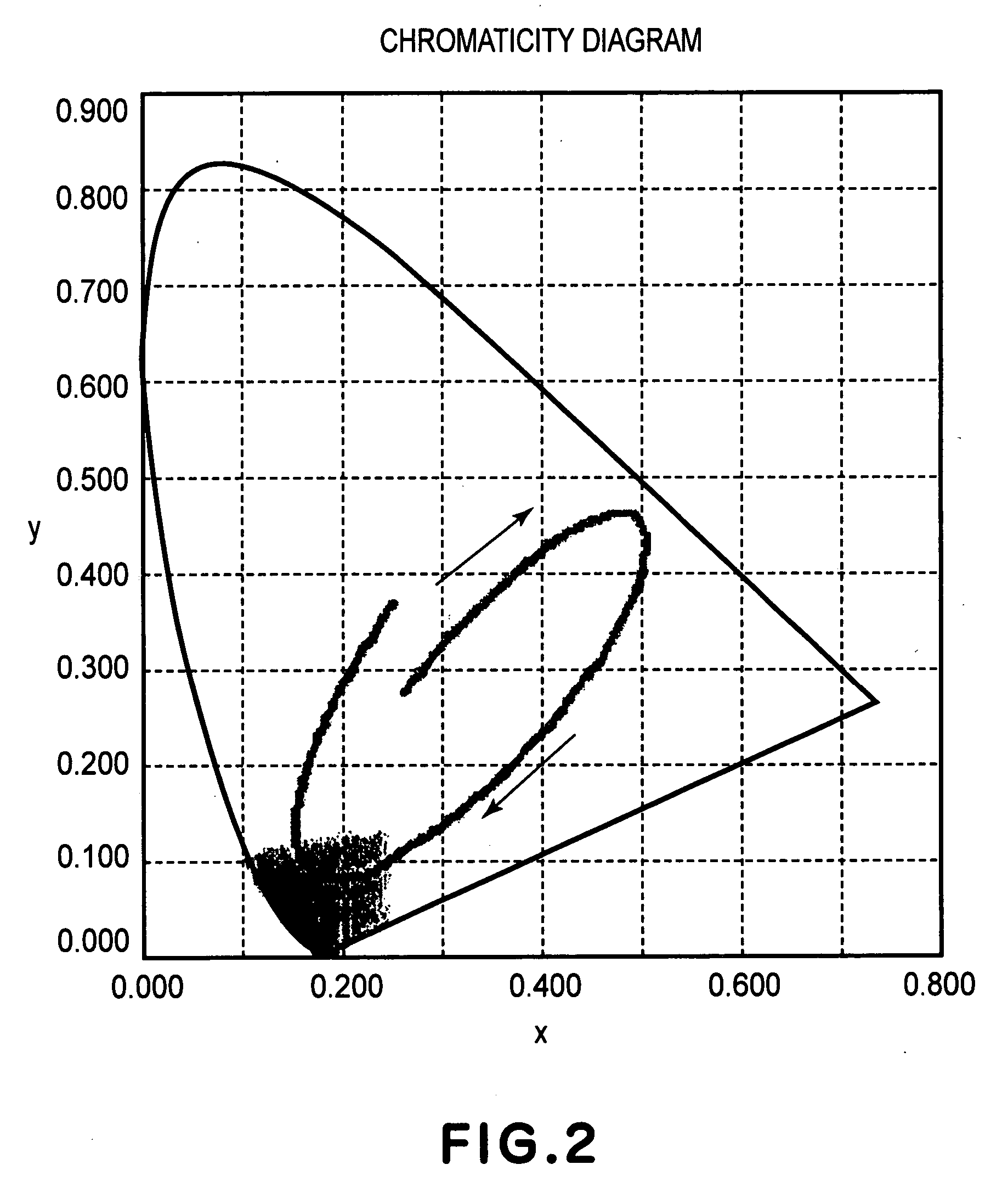
[0127] When such a liquid crystal display device is subjected to image display by changing the voltage, with respect to the second subpixels 51 with the green color filter, a change in transmittance depending on the applied voltage value is shown in an area of not more than 3 V to provide a continuous gradation characteristic. On the other hand, with respect to the first subpixels 52 be...

embodiment 2

[0136] A pixel constitution of a liquid crystal display device used in Embodiment 2 is given, as shown in FIG. 12, by dividing one unit pixel into two subpixels and providing a green color filter to and a magenta color filter to a first subpixel 52. Incidentally, similarly as in FIG. 1, the liquid crystal display device includes unit pixels of 1200 in columns and 600 in rows, and the cell thickness of this device 5 microns.

[0137] When such a liquid crystal display device is subjected to image display by changing the voltage, with respect to the subpixels with the green color filter, a change in transmittance depending on the applied voltage value is shown in an area of not more than 3 V to provide a continuous gradation characteristic. On the other hand, with respect to the first subpixels 52 provided with the magenta color filter, blue display is effected under application of 5 V and red display is effected under application of 3.8 V, so that it is found that the liquid crystal pa...

embodiment 3

[0144] A pixel constitution of a liquid crystal display device used in Embodiment 3 is given, as shown in FIG. 13, by dividing one unit pixel into three subpixels and providing a green color filter to one second subpixel 51 and a magenta color filter to remaining two first subpixel 52a and 52b at an areal ratio of 1:2. Incidentally, similarly as in FIG. 1, the liquid crystal display device includes unit pixels of 800 in columns and 600 in rows, and the cell thickness of this device 5 microns. Further, in this case, when a voltage of ±5 V is applied to the magenta subpixels at the first subpixels 52 provided with the magenta color filter, an amount of retardation is about 300 nm.

[0145] When such a liquid crystal display device is subjected to image display by changing the voltage, with respect to the subpixels with the green color filter, a change in transmittance depending on the applied voltage value is shown in an area of not more than 3 V to provide a continuous gradation charac...


PUM

PropertyMeasurementUnit
thicknessaaaaaaaaaa
thicknessaaaaaaaaaa
thicknessaaaaaaaaaa

Abstract

Unit pixels in a color display device each include a first and a second subpixel. The second is provided with a color filter, and each has a medium changing optical properties (hue and brightness of transmitted light) depending on an applied voltage. A voltage is applied to the first subpixel to modulate those optical properties of the medium and a voltage is applied to the second subpixel to modulate the brightness of light passing through the medium disposed at the second subpixel. When display of the color display device is switched, a correction voltage of the second subpixel is calculated from a voltage applied to the first subpixel before the display is switched and a voltage applied to the first subpixel after the display is switched, and the voltage applied to the second subpixel is set to a value obtained by superposing the correction voltage on a voltage determined by the display at the second subpixel in a predetermined period after the voltage applied to the first subpixel is switched. The correction voltage modifies the color of the second subpixel so as to produce an achromatic color at that unit pixel by mixing a chromatic color, transitionally appearing at the first subpixel when the display is switched, with the color of the second subpixel.

Description

TECHNICAL FIELD [0001] The present invention relates to a color display device. BACKGROUND OF THE INVENTION [0002] Heretofore, there is a display apparatus provided with a display device which effects color display depending on three types of signals corresponding to images of three colors of red, green and blue. As such a display apparatus, there are various display devices such as CRT, plasma display (PDP), organic EL display (OLED), and these display apparatuses have already been widely put into practical use. Among them, the LCD has characteristics, such as a thin shape, a low power consumption, and a high display quality, so that it is applied to every color display apparatus, such as a cellular phone, a monitor for PC, a home television, and the like. [0003] Almost all the color display methods of the LCD employ a microcolor filter (MCF) method wherein a liquid crystal display device capable of performing monochromatic modulation is used and one pixel is divided into three sub...

Claims


Application Information

Patent Timeline
Patent Type & Authority Applications(United States)
IPC IPC(8): G09G5/10G02F1/1335G02F1/133G02F1/1343G02F1/139G09G3/20G09G3/36
CPCG02F1/133514G02F1/1393G02F2001/134345G09G3/2011G09G3/2044G09G3/2074G09G2340/16G09G2300/0452G09G2300/0491G09G2310/06G09G2320/0242G09G2320/0261G09G2320/103G09G3/3607G02F1/134345
Inventor ASAO, YASUFUMIISOBE, RYUICHIRO
Owner CANON KK
Why Eureka
Try Eureka