
Active matrix display with variable duty cycle

a technology of active matrix and duty cycle, applied in static indicating devices, instruments, non-linear optics, etc., can solve the problem of not having freedom to adjust the duty cycle, and achieve the effect of shortening the duty cycle, reducing the duty cycle, and increasing the update frequency of the corresponding pixel group

Inactive Publication Date: 2006-01-19
INNOLUX CORP
View PDF15 Cites 23 Cited by
  • Summary
  • Abstract
  • Description
  • Claims
  • Application Information

AI Technical Summary

Benefits of technology

[0012] Thus, the invention is based upon the fact that the dominating degradation mechanisms can be determined, and that an active display can be configured to drive the pixels at their individually most optimal duty cycle. Therefore, the invention enhances the lifetime of a fall color active matrix polymer (organic) light emitting diode (AMP(O)LED) display by introducing a pixel dependent variable duty cycle to the display.
[0034] Clearly, the shorter the duty cycle, the higher the light output should be to achieve the perception of the required average light output. A shorter duty cycle however has the general advantages of reducing motion artifacts and increasing display uniformity.

Problems solved by technology

Unfortunately, in passive matrix devices there is no freedom to adjust the duty cycle since this is rigidly fixed to the multiplex ratio.

Method used


Image

  • Active matrix display with variable duty cycle
  • Active matrix display with variable duty cycle
  • Active matrix display with variable duty cycle

Examples


Embodiment Construction

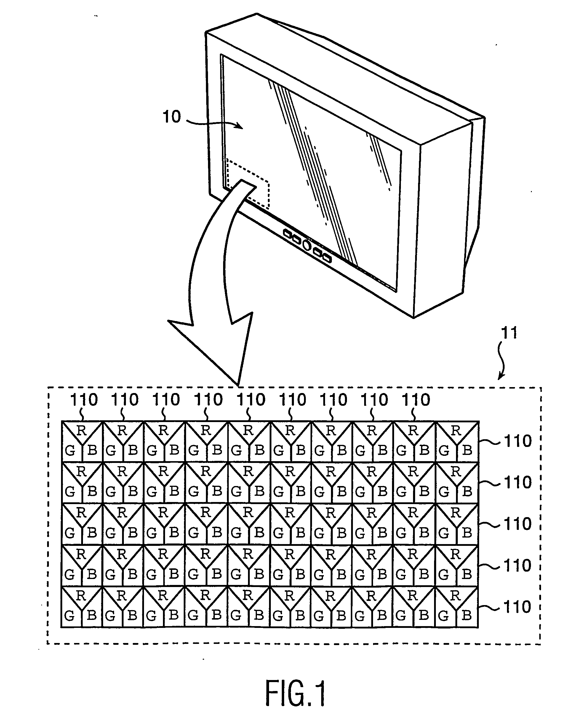
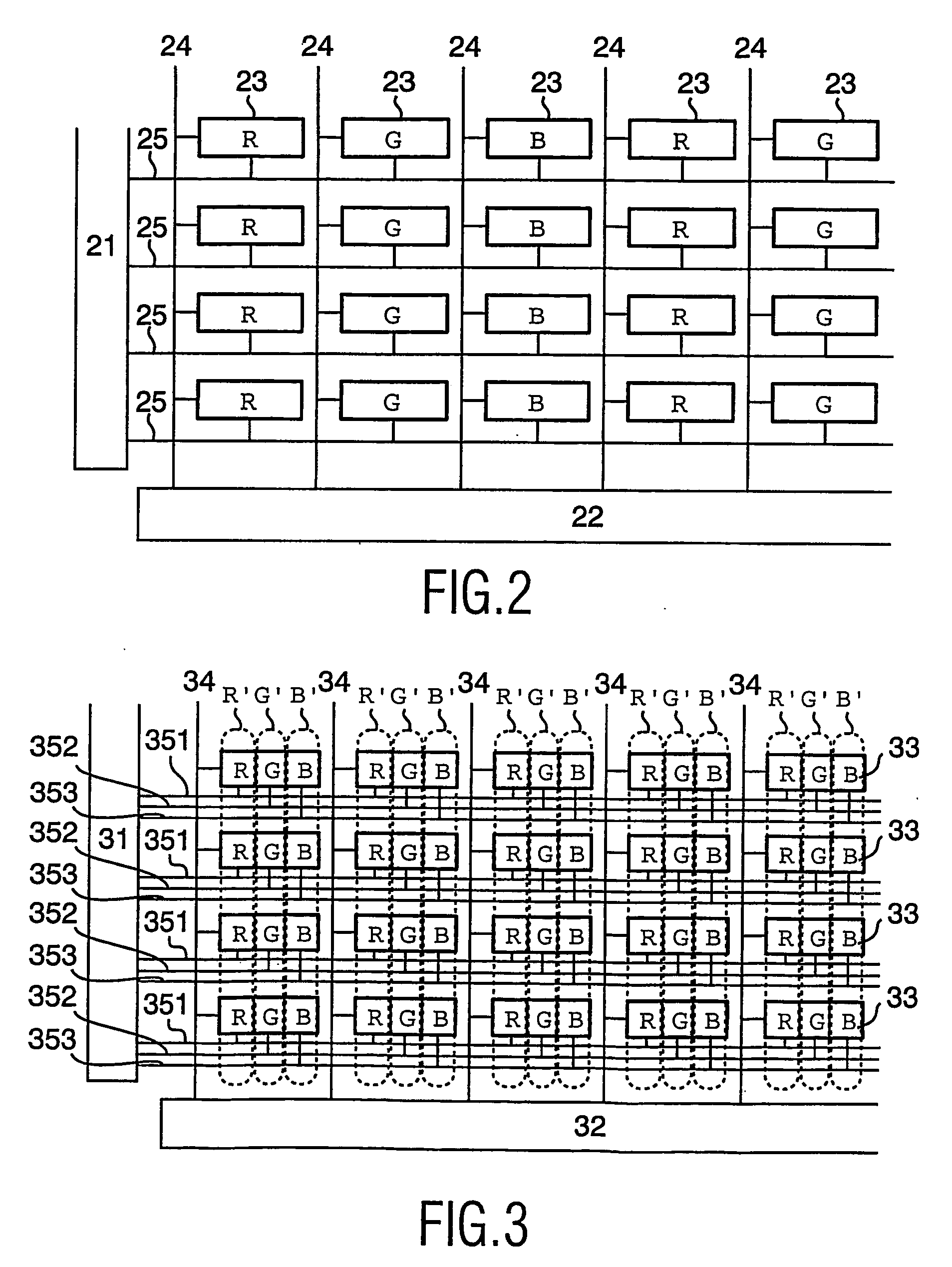
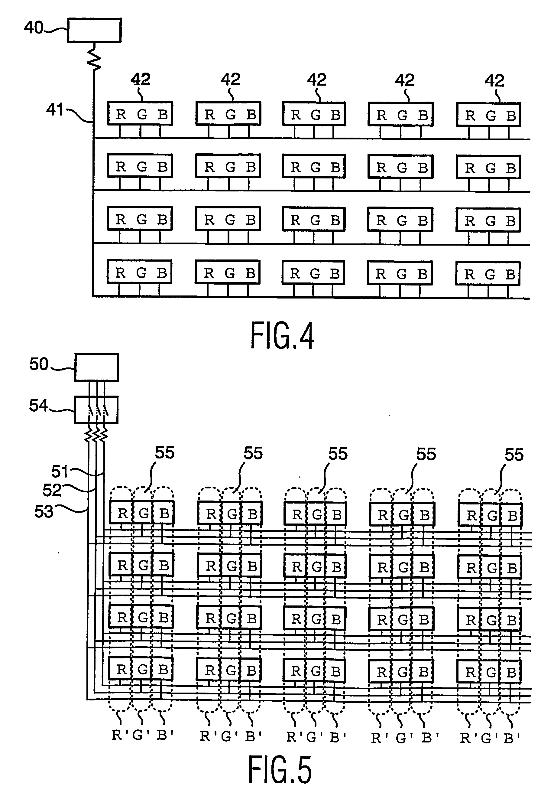
[0046]FIG. 1 schematically shows an active matrix RGB display device 10, and an enlarged part 11 of one corner of its screen. The display device 10 comprises a multiplicity of pixels 110. The pixels 110 comprised in the display device are RGB pixels, each comprising a red R, a blue B and a green G subpixel. Typically, when implementing the invention in a display device having multiple colored pixels 110, i.e. each pixel 110 has a number of subpixels R, G, B, the grouping of pixels is done such that each type of subpixel is grouped in the same pixel group R′, G′, B′. Thereby, each pixel is in a sense related to every pixel group, but each subpixel is only related to one pixel group. In a conventional display device, as schematically disclosed in FIG. 2, a row (or select) driver 21 and a column (or data) driver 22 are connected to, and address the subpixels 23 by, a row line 25 and a column line 24, respectively. Furthermore, as disclosed in FIG. 4, the pixels 42 (having subpixels R, ...


PUM


Abstract

The invention relates to an active matrix display device (10) having a plurality of pixels (110). The pixels are grouped into pixel groups (R′, G′, B′). Each pixel group (R′, G′, B′) is assigned a specific duty cycle, such that at least two pixel groups are assigned different duty cycles. The device furthermore comprises circuitry (54) for driving each pixel group (R′, G′, B′) at its assigned duty cycle. The invention also relates to the driving of such display devices.

Description

FIELD OF THE INVENTION [0001] This invention relates to active matrix display devices and to methods for driving pixels in such display devices. TECHNICAL BACKGROUND [0002] Display devices employing electroluminescent, light-emitting, display elements are well known. The display elements may comprise organic thin film electroluminescent elements, using, for example, organic materials, or other light emitting diodes (LEDs), using traditional III-V semiconductor compounds. [0003] Recent developments in organic electroluminescent materials, particularly polymer materials, have demonstrated their ability to be used practically for video display devices. These materials typically comprise one or more layers of an electroluminescent material, for example a semiconducting conjugated polymer, sandwiched between a pair of electrodes, one of which is transparent and the other is of a material suitable for injecting holes or electrons into the polymer layer. The polymer material can be fabrica...

Claims


Application Information

Patent Timeline
Patent Type & Authority Applications(United States)
IPC IPC(8): H04N9/47H01L51/50G09G3/20G09G3/30G09G3/32G09G3/36
CPCG09G3/2014G09G3/2022G09G2330/021G09G3/3648G09G2320/043G09G3/3208G09G3/20G09G3/30
Inventor ROSMALEN, GERARD EDUARD
Owner INNOLUX CORP
Learn More