Illuminator for dark field inspection

a technology of illumination and dark field, applied in the field of inspection of materials, can solve the problems of affecting the overall performance of the inspection system, the sensitivity of the inspection system can vary, and the “ring-lamp” device, similar to the one used to illuminate dark-field microscopes, cannot work well for the inspection system of dark-field wafers

Inactive Publication Date: 2006-01-19
AUGUST TECH
View PDF3 Cites 36 Cited by
  • Summary
  • Abstract
  • Description
  • Claims
  • Application Information

AI Technical Summary

Benefits of technology

[0009] Advantageously, the present invention provides for a dark-field illumination system that is compact, or illuminates a large illumination region on the target, or provides uniform illumination and a uniform angular spectrum across an illumination region on the target

Problems solved by technology

The illumination for a dark-field system greatly affects the overall performance of the inspection system.
For instance, a “ring-lamp” device, similar to those used to illuminate dark-field microscopes, does not work very well for the dark-field wafer inspection s

Method used


Image

  • Illuminator for dark field inspection
  • Illuminator for dark field inspection
  • Illuminator for dark field inspection

Examples


Embodiment Construction

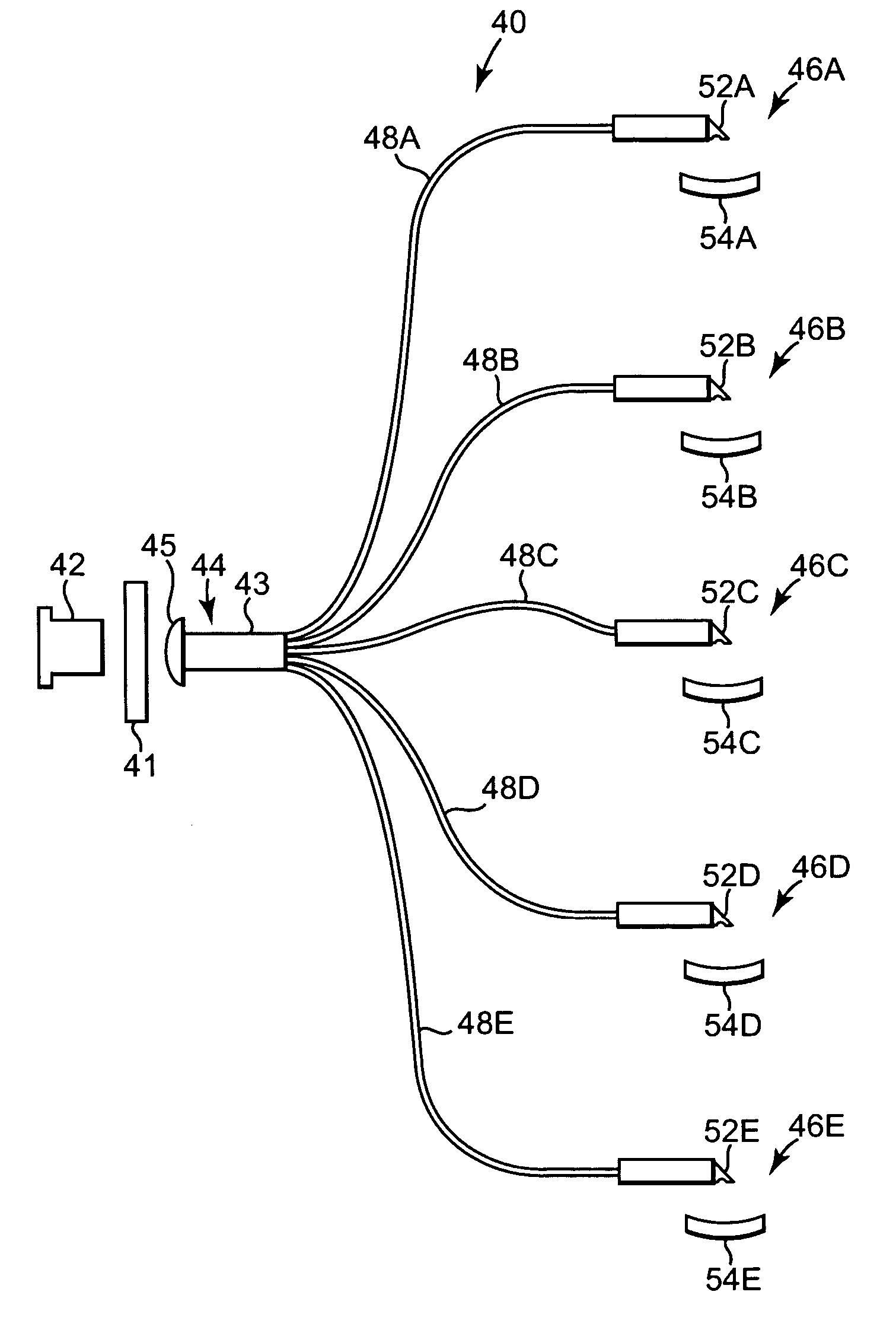
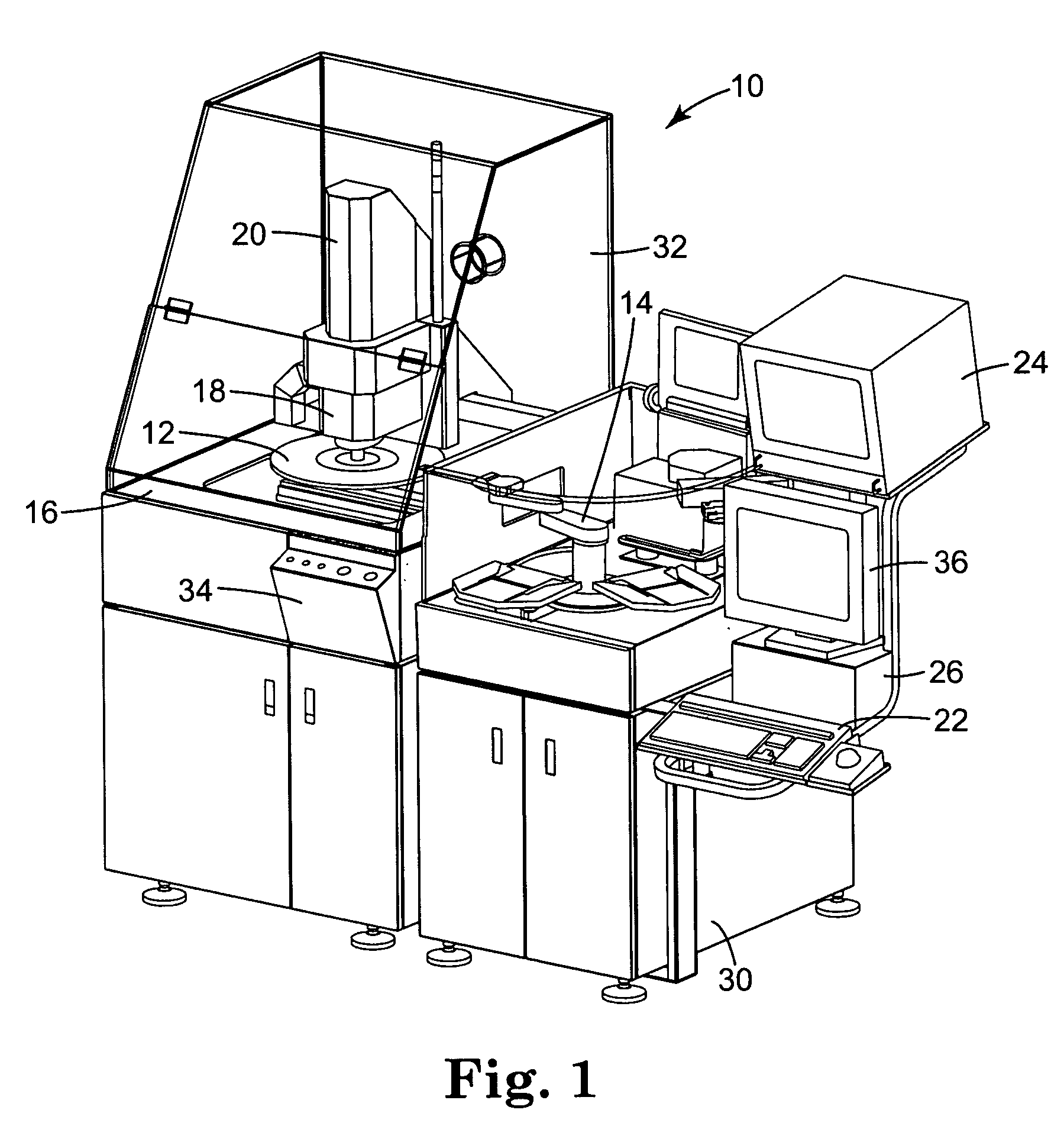
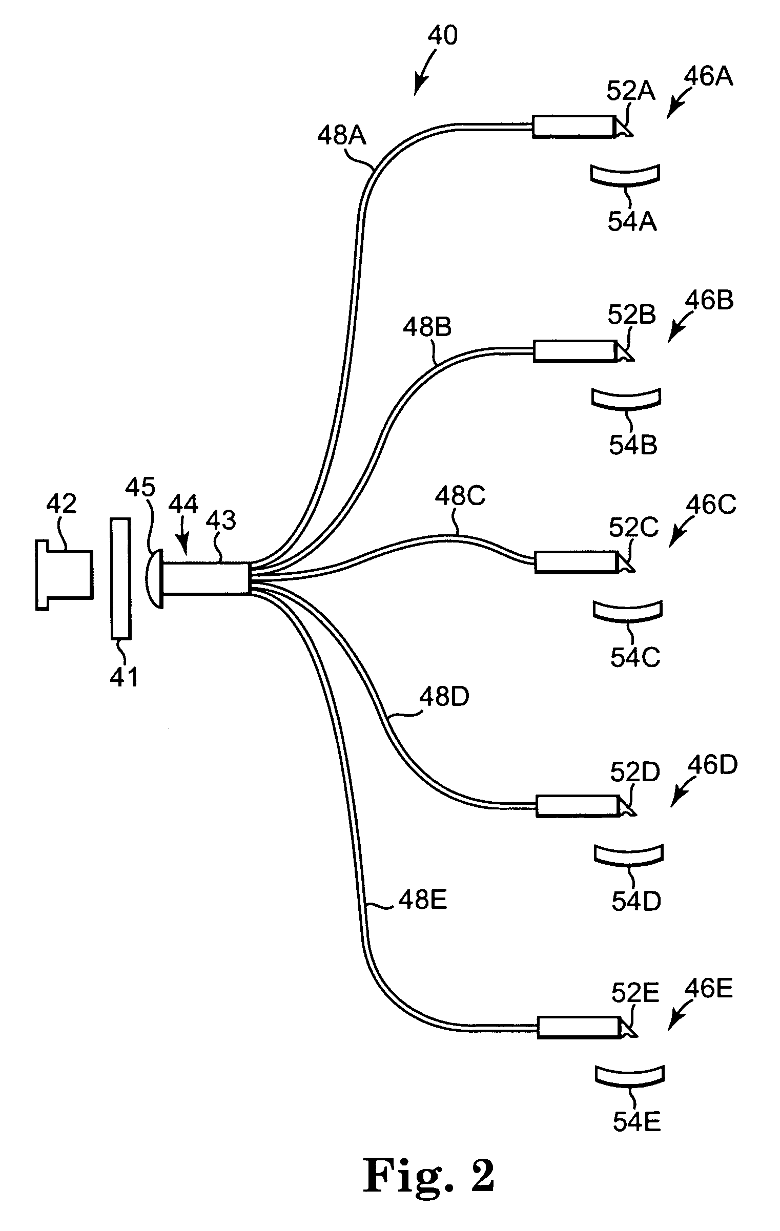
[0026] The present invention is directed to illuminators for dark-field inspection systems, which are commonly used in systems that visually inspect wafers for defects during a particular manufacturing process. An example of a wafer inspection system is shown in FIG. 1.

[0027] A typical wafer inspection system 10 is used in one environment to inspect whole wafers before die have been fabricated on them, but may also be used to inspect patterned whole wafers, die diced from patterned wafers, sawn wafers, broken wafers, wafers of any kind on film frames, die in gel paks, die in waffle paks, MCMs, JEDEC trays, Auer boats, and other wafer and die configurations, whether or not packaged. Hereafter, all of these uses shall be referred to generally as inspection of wafers. System 10 includes a wafer test plate 12, an actuator 14 that moves the wafer to the test plate 12, a wafer alignment device 16 for aligning each and every wafer at the same x, y, and angular location or x, y, z, and ang...


PUM


Abstract

Light from a single source is divided among several illumination arms, each of which directs light via a multimode fiber bundle from the source to the wafer location. The arms are arranged circumferentially around a common illumination region, so that the region is illuminated from several directions. For each arm, light exiting the fiber bundle enters a turning prism, reflects off the hypotenuse of the prism, and is diverged in one dimension by a negative cylindrical surface on the exiting face of the prism. The beam then reflects off an anamorphic mirror and propagates to the illumination region on the wafer. The beam has an asymmetric footprint, so that it illuminates a nearly circular region of the wafer when viewed at normal incidence. The fiber bundle is at the front focal plane in the meridional dimension. The illumination region is at the rear focal plane in both dimensions.

Description

CROSS-REFERENCE TO RELATED APPLICATIONS [0001] This application claims the benefit of U.S. Provisional Patent Application No. 60 / 587,206, filed Jul. 12, 2004, which is hereby incorporated by reference in its entirety.BACKGROUND OF THE INVENTION [0002] 1. Field of the Invention [0003] The present invention relates to inspection of materials, and more particular to illuminators for dark-field inspection of material, inspection systems for dark-field inspection of material, and methods for illuminating a target for dark-field inspection. [0004] 2. Description of the Related Art [0005] As more manufacturing processes use wafer-based technology, and utilize increasingly smaller features on these wafers, it becomes increasingly important to inspect the wafers for defects at various stages throughout the manufacturing process. Wafer inspection systems have evolved to keep pace with these demanding requirements. [0006] In a typical wafer inspection system, a wafer is attached to a movable s...

Claims


Application Information

Patent Timeline
IPC IPC(8): G01N21/88
CPCG01N21/8806G01N2021/8822G01N21/9501
Inventor VAUGHNN, DAVID
Owner AUGUST TECH
Why Eureka
Try Eureka