Ultrasonic transmitting/receiving apparatus and scanning sonar employing same

a scanning sonar and transmitting/receiving technology, applied in the field of ultrasonic transmitting/receiving apparatus and scanning sonar, can solve the problems of slow detection of detected images, inability to detect quick changes, and difficulty in reading and understanding the relation between images while comparing them, so as to avoid interference

Active Publication Date: 2006-01-19
FURUNO ELECTRIC CO LTD
View PDF4 Cites 54 Cited by
  • Summary
  • Abstract
  • Description
  • Claims
  • Application Information

AI Technical Summary

Benefits of technology

[0009] Embodiments of the present invention make it possible to perform a detecting operation by transmitting / receiving ultrasonic signal in lateral direction or longitudinal direction in a short time period. Another embodiment of the present invention provides an ultrasonic transmitting / receiving apparatus and a scanning sonar which are capable of avoiding an interference caused by a receiving signal other than an intended receiving signal.
[0012] An ultrasonic transmitting / receiving apparatus is disclosed wherein the transmitting beam former forms transmitting beams by transmitting signals with different frequency at the same time at every transmitting beam. This leads to reducing duration of transmitting beam formation, the duration is the same as in the case of forming transmitting beam in a single direction, and detection can be performed at short time intervals.
[0013] In an ultrasonic transmitting / receiving apparatus according to an embodiment of the invention, the transmitting beam former forms transmitting beams by time-sharing during transmitting beam formation, and receiving beam forming means extracts a received signal during receiving beam formation following the duration of transmitting beam formation. Transmitting beams are formed sequentially in a plurality of directions such as in lateral direction and longitudinal direction and the received signal from each directions is extracted in a subsequent duration of receiving beam formation following the duration of transmitting beam formation. Therefore detecting time interval remains the same or detections in a plurality of directions (lateral direction and longitudinal direction) is performed at short time intervals. And yet each transducer element is driven by a single frequency signal, which saves transmitting power and enable detection to reach farther place.
[0015] Therefore the data transmission to the driving circuit attached to every transducer element becomes easy and noise affection can be reduced. Also digital signal is obtained for every received signal of each transducer element, which leads to easy transmission of received signal of the each transducer element to a processing part, and yet the phase control and filtering is performed through digital calculation, which allows for easier noise reduction.

Problems solved by technology

This causes to make it slow to renew the detected image, in other words images which shows quick change cannot be detected.
Also when the two detected images from the horizontal mode and the vertical mode are displayed on the same screen, the time those two images are detected is different (neither the same nor close to each other), which leads to difficulty in reading and understanding the relation therebetween while comparing the two images.
The problem described above arises not only in the above case, but also in the case where both objects in lateral direction, i.e. direction horizontal or direction tilted from horizontal by specific angle and objects in longitudinal direction, i.e. direction vertical or direction tilted from vertical by specific angle are tried to be detected in the same time or within a short period of time.
This makes, however, the detecting operation intermittent and it difficult to perform detection in a short time period.

Method used


Image

  • Ultrasonic transmitting/receiving apparatus and scanning sonar employing same
  • Ultrasonic transmitting/receiving apparatus and scanning sonar employing same
  • Ultrasonic transmitting/receiving apparatus and scanning sonar employing same

Examples


Embodiment Construction

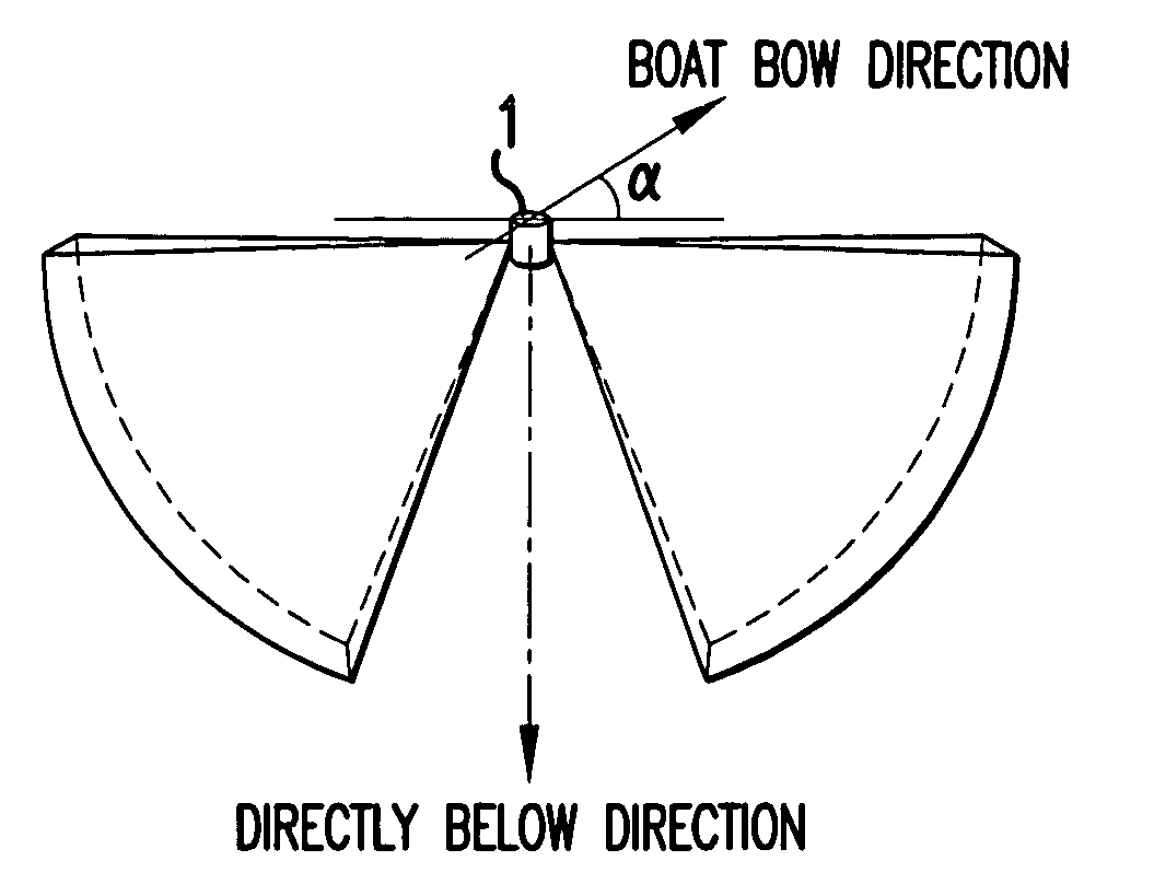
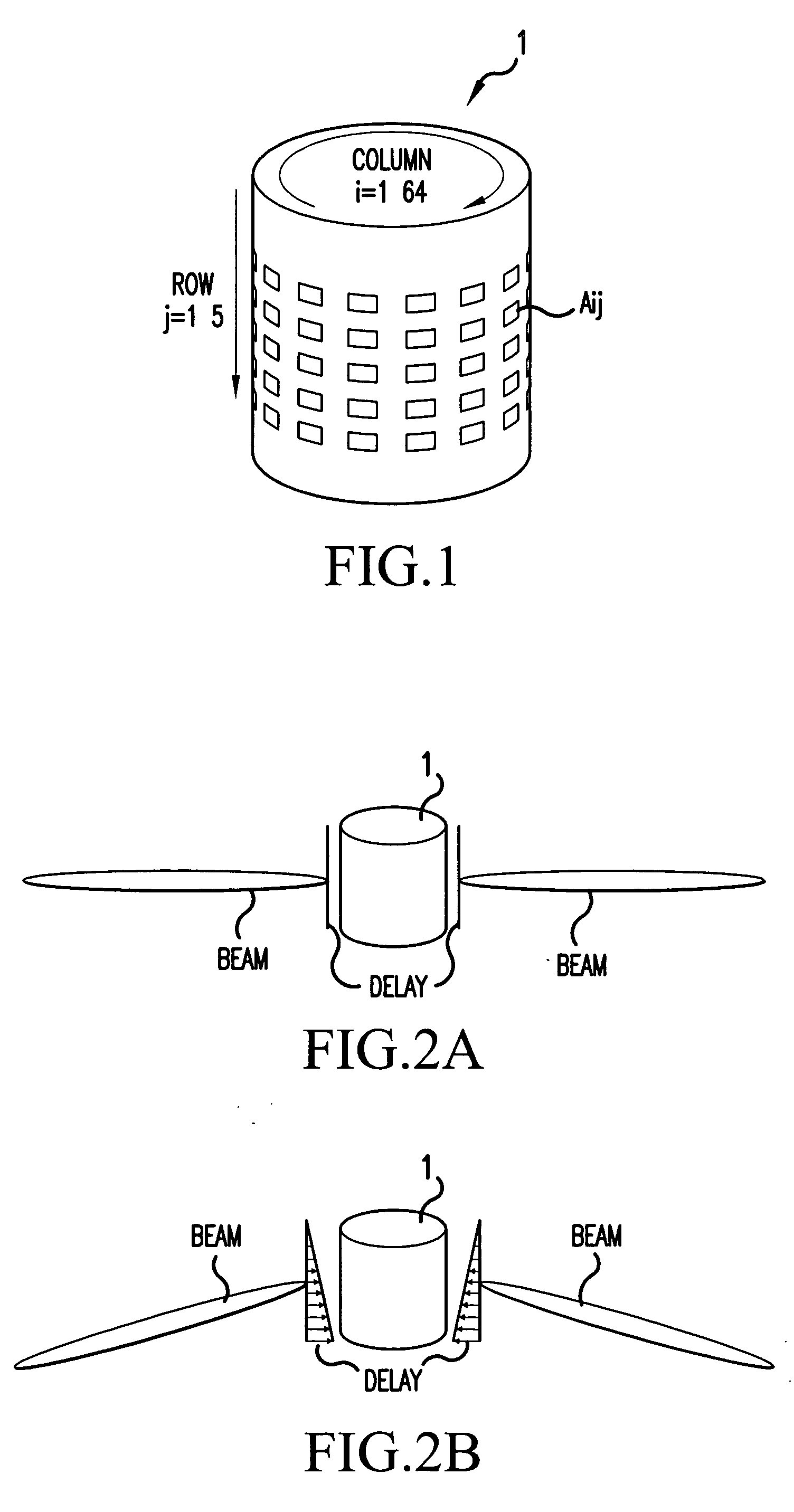
[0034] A scanning sonar of the invention is described referring to the drawings which are intended to illustrate embodiments of the invention only and not to limit same. FIG. 1 is a schematic diagram of a transducer used for the scanning sonar. As shown in FIG. 1, a transducer 1 is constituted by 320 transducer elements Aij (i=1 to 64, j=1 to 5) consisting of 5 rows and 64 columns. The transducer 1 is mounted on the bottom of a boat so that the axis of the cylinder is vertical.

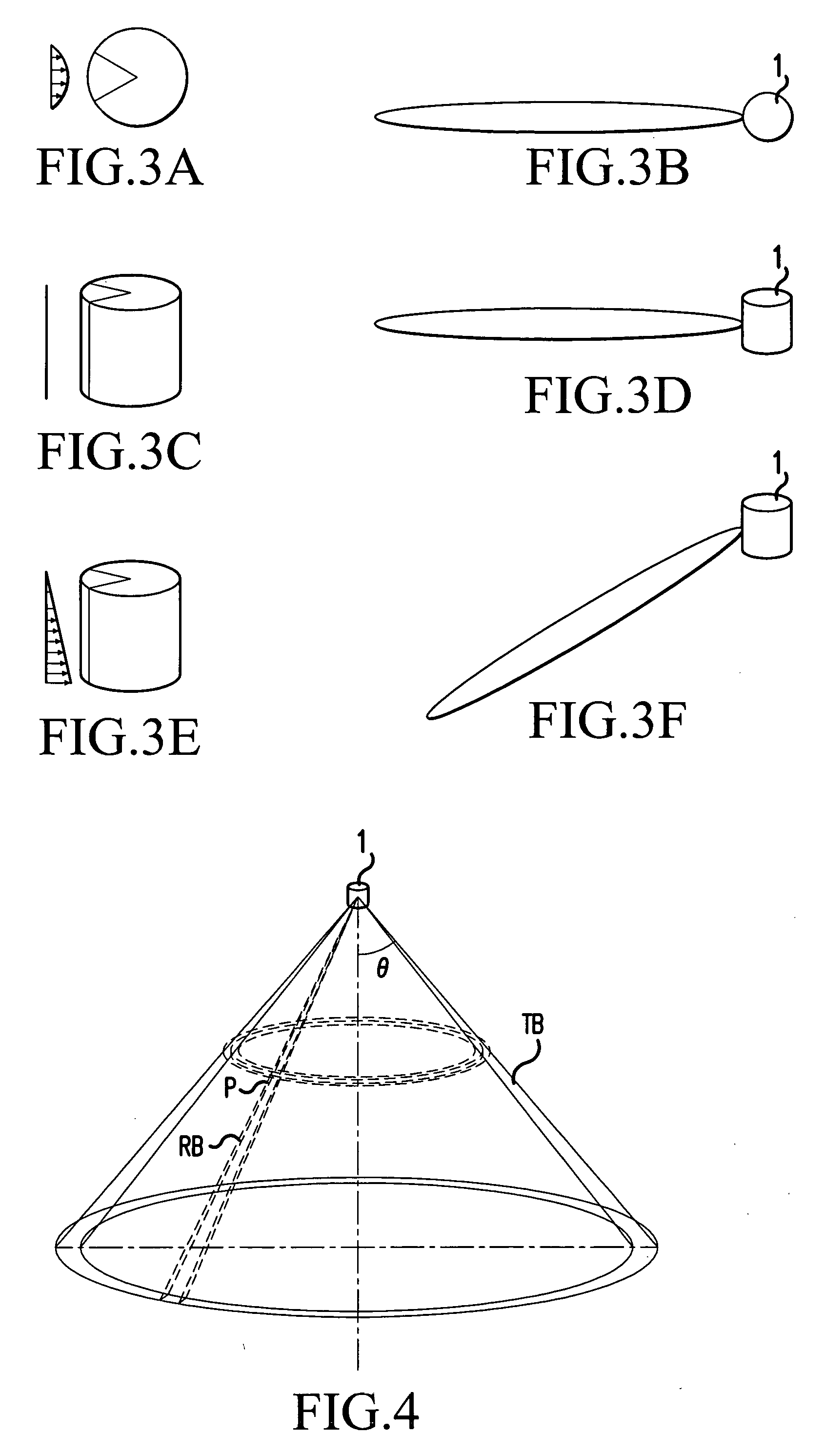
[0035]FIG. 2 is an explanatory diagram of a transmitting beam. FIG. 2(A) shows a directivity of a transmitting beam formed when the scanning detection is performed in all directions (in full circle) in a horizontal plane. FIG. 2(B) shows a transmitting beam formed when the scanning detection is performed in all directions (in full circle) at a specific tilt angle. The transmitting beam can be tilted downwardly by a specific angle to form an umbrella type beam by providing the greater delay time to the lower p...


PUM


Abstract

An ultrasonic apparatus is disclosed that includes a transducer having a plurality of transducer elements, a controller operatively connected to the transducer and driving the transducer elements to produce a first ultrasonic transmitting beam having a first frequency and a second ultrasonic transmitting beam having a second frequency; and a processor operatively connected to said transducer for forming and moving reception beams to receive echo signals and extracting frequency components corresponding to said first ultrasonic transmitting beam and said second ultrasonic transmitting beam.

Description

FIELD OF THE INVENTION [0001] This invention relates to an ultrasonic transmitting / receiving apparatus and a scanning sonar for detecting underwater objects by transmitting / receiving ultrasonic waves. BACKGROUND OF THE INVENTION [0002] A scanning sonar has been used for detecting underwater objects. The scanning sonar includes an approximate cylindrical transducer to detect an object in all directions around the transducer as shown in FIG. 1. Each vibrator of the transducer is driven to form an ultrasonic transmitting beam in all directions therearound. Signals for driving each of transducer elements (vibrator) are controlled to provide a transducer element array in each row with an appropriate delay time or phase difference so that a transmitting beam, which has specific umbrella type tilt angle keeping a directivity in vertical direction being within the specific angle, can be formed. A detection over all directions can be made by turning a direction of a receiving beam sequential...

Claims


Application Information

Patent Timeline
Patent Type & Authority Applications(United States)
IPC IPC(8): G01S15/89
CPCG01S15/107G01S15/96
Inventor NISHIMORI, YASUSHIHANDA, MINORUOZASA, SHIROH
Owner FURUNO ELECTRIC CO LTD
Why Eureka
Try Eureka