Al technical title is built by PatSnap Al team. It summarizes the technical point description of the patent document.
a rotational plate and prosthesis technology, applied in the field of knee prosthesis, can solve the problems of exacerbated drawbacks, difficulty in inserting the plastic tibia plate, and the type of prosthesis has the drawback of not physically embodying an axis of rotation
Inactive Publication Date: 2006-01-19
CORIN
View PDF74 Cites 103 Cited by
Summary
Abstract
Description
Claims
Application Information
AI Technical Summary
This helps you quickly interpret patents by identifying the three key elements:
Problems solved by technology
Method used
Benefits of technology
[0014] The knee prosthesis according to the present invention is intended to provide a plastic tibia plate which has a degree of freedom in rotation with respect to the metal base.
[0019] The knee prosthesis according to the present invention comprises additional guide mechanism which is secured to a device making it possible to prevent the tibia plate from lifting from the metal base.
[0031] The knee prosthesis according to the present invention comprises an upstand which is integral with a flange which engages in a slot in the housing to prevent the tibia plate from lifting off the metal base as the plate slides in rotation about the center of rotation.
[0042] The knee prosthesis according to the present invention has a short height of the guide mechanism and of their anterior positioning on the metal base which allows the tibia plate to be mounted on the base via a strictly anterior approach, the plate requiring upward clearance only by the height of the guide mechanism.
Problems solved by technology
These connecting devices have certain drawbacks, namely the difficulty of inserting the plastic tibia plate once the metal base is in place on the tibia.
These drawbacks are exacerbated when the posterior cruciate ligament is being kept, as this restricts access to the upper part of the tibia.
This type of prosthesis has the drawback of not physically embodying an axis of rotation.
Method used
Image
Click on the blue label to locate the original text in one second.
Reading with bidirectional positioning of images and text.
Examples
Embodiment Construction
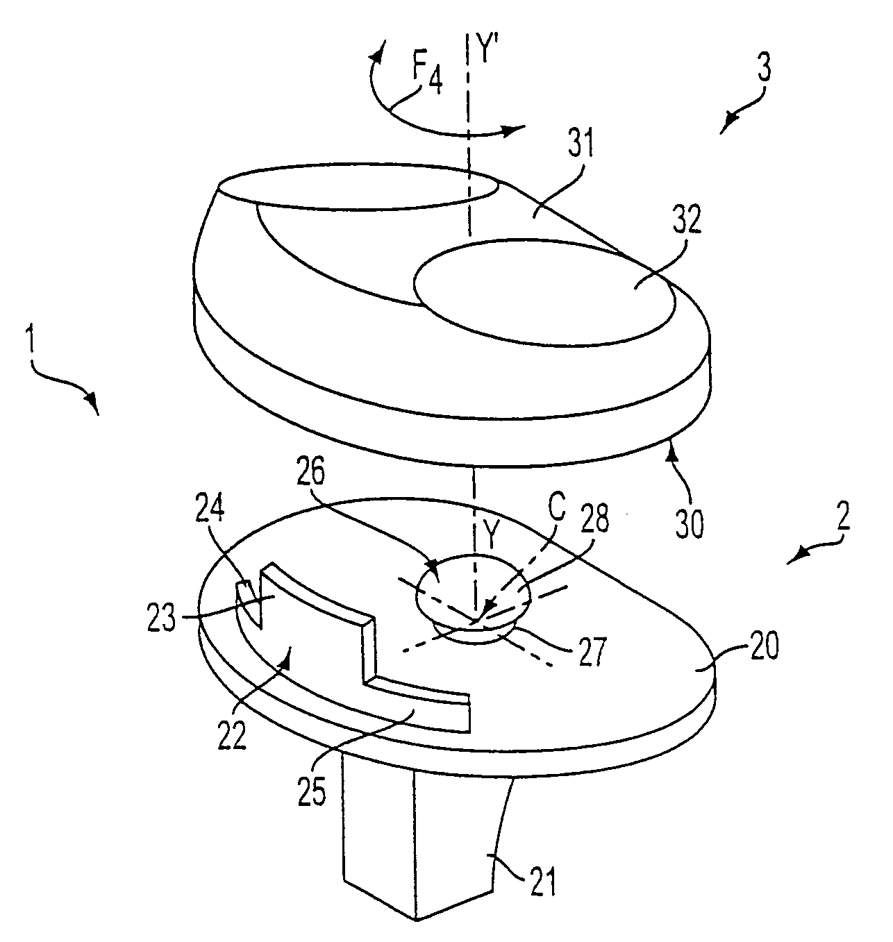
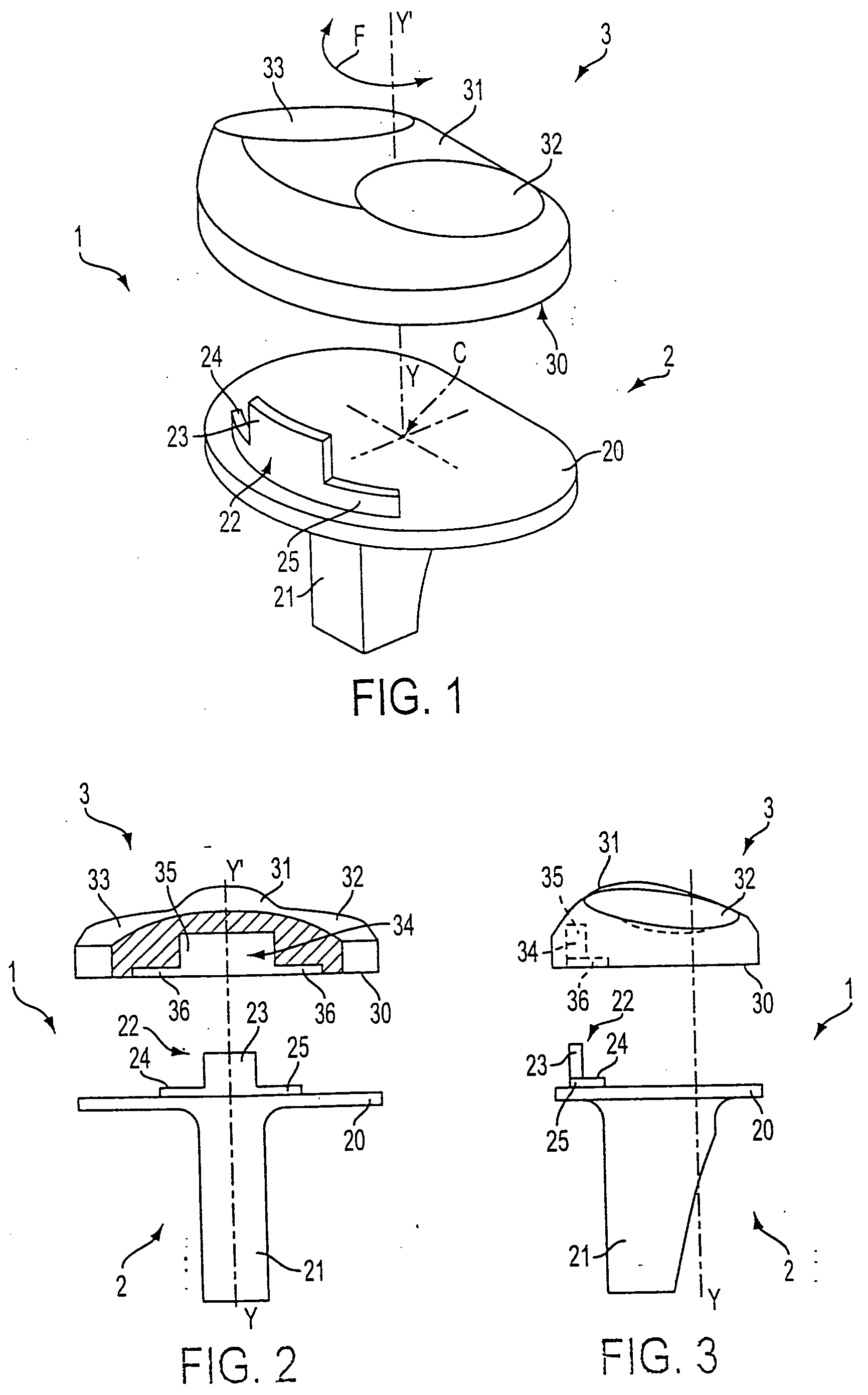
[0054] FIGS. 1 to 3 show a knee prosthesis 1 comprising a metal base 2 and a tibia plate 3, whereas the femoral element is not depicted.
[0055] The metal base 2 consists of a horizontal disk 20 secured on one of its faces to an anchoring rod 21 allowing the base 2 to be fixed into the tibia of a patient.
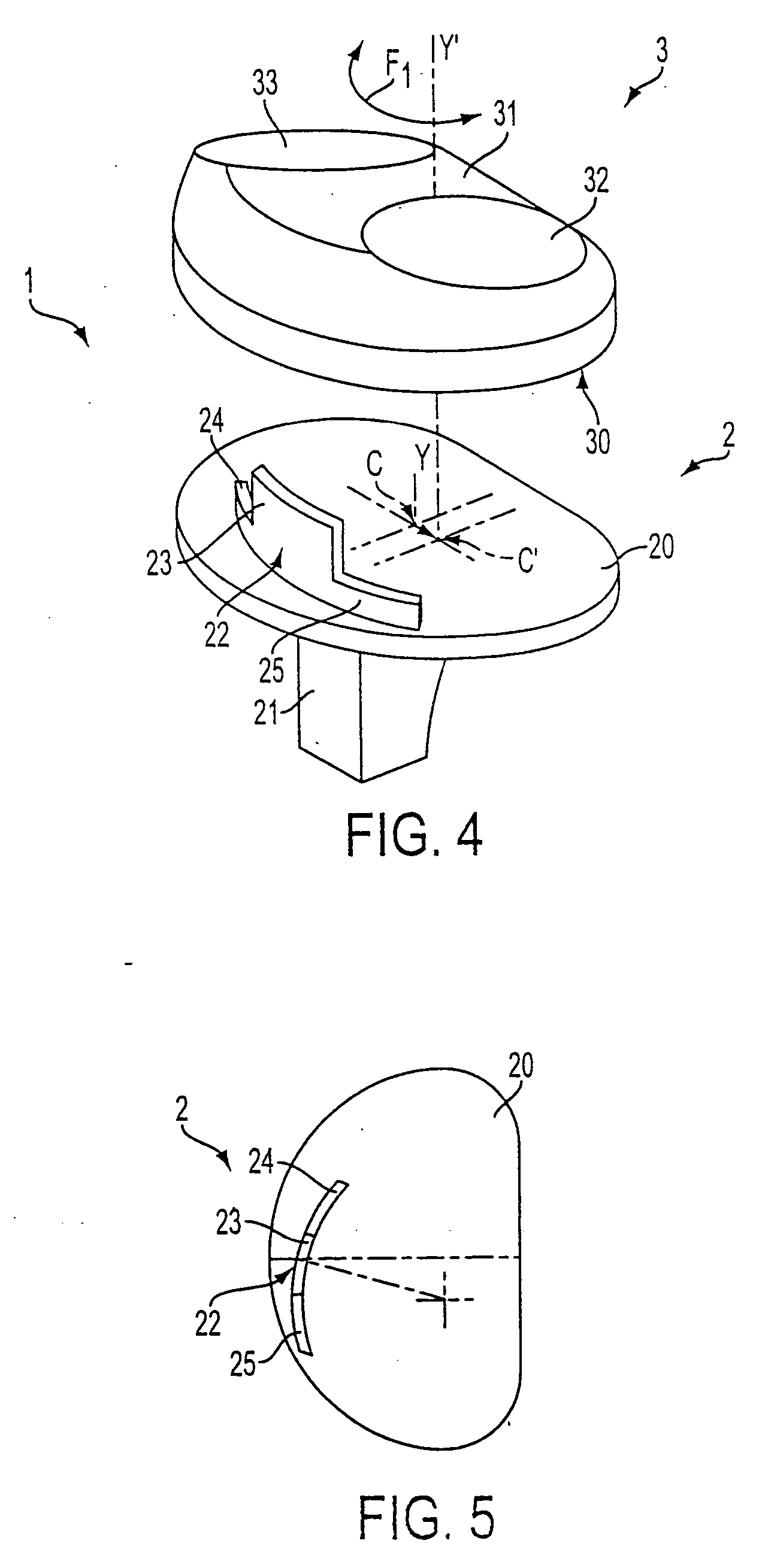
[0056] The horizontal disk 20 comprises, on the opposite side to the rod 21, a guide mechanism which utilizes an upstand 22 with an exterior profile in the shape of an arc of a circle. In this case, note that the center of rotation C of the upstand 22 is borne by the tibia bone vertical axis YY′.
[0057] The upstand 22 extending vertically above the horizontal disk 20 has a central part 23 integral on each side with two vertical edges 24 and 25 which are not as tall as the central part 23.
[0058] In addition, the upstand 22 is positioned on the horizontal disk 20 of the metal base 2 a certain distance away from the center of rotation C.
[0059] The tibia plate 3, which is made of plas...
PUM
Abstract
The knee prosthesis with rotary plate comprises a metal base (2) and a tibia plate (3) which are equipped with guide means (22, 22′, 22″, 26, 29, 5, 6, 5′, 9, 50, 51, 52, 13, 15, 18; 34, 34′, 34″, 35, 37, 7, 8, 10, 12, 53, 54, 55, 10′, 17) defining a center of rotation (C, C′) which may be offset from that of the tibia bone axis (YY′), so as to allow the tibia plate (3) to slide in rotation over the said base, the said guide means being positioned a certain distance away from the center of rotation (C, C′).
Description
CROSS-REFERENCE TO RELATED APPLICATIONS [0001] This application is a Continuation of application Ser. No. 09 / 832,874, filed Apr. 12, 2001 in the name of the same inventors which is a Continuation of application Ser. No. 09 / 158,791, filed Sep. 23, 1998, now U.S. Pat. No. 6,299,646, issued Oct. 09, 2001, also in the name of the same inventors. The entire contents of the prior applications is incorporated herein by reference. This application also claims priority benefits of French Patent Application FR 97 12042, filed Sep. 23, 1997.BACKGROUND OF THE INVENTION [0002] 1. Field of the Invention [0003] The present invention relates to a knee prosthesis and more specifically to the device for assembling its tibia plate, which is made of plastic, on its metal base anchored beforehand into the tibia bone tissue. [0004] 2. Discussion of the Background Information [0005] Knee prostheses which comprise a plastic tibia part which is free to rotate about the tibia bone axis with respect to the me...
Claims
Application Information
Patent Timeline
Application Date:The date an application was filed.
Publication Date:The date a patent or application was officially published.
First Publication Date:The earliest publication date of a patent with the same application number.
Issue Date:Publication date of the patent grant document.
PCT Entry Date:The Entry date of PCT National Phase.
Estimated Expiry Date:The statutory expiry date of a patent right according to the Patent Law, and it is the longest term of protection that the patent right can achieve without the termination of the patent right due to other reasons(Term extension factor has been taken into account ).
Invalid Date:Actual expiry date is based on effective date or publication date of legal transaction data of invalid patent.
Patent Type & Authority Applications(United States)