
Onboard supplemental power system at varying high altitudes

Active Publication Date: 2006-01-26
STEWARD DAVIS INT
View PDF39 Cites 13 Cited by
  • Summary
  • Abstract
  • Description
  • Claims
  • Application Information

AI Technical Summary

Problems solved by technology

However, standard aircraft production-design characteristics generally leave little, if any, room for significant electrical or cooling air systems expansion or modification.
Thus, it is difficult for aircraft to accommodate post-production systems additions.
The traditional approach of original equipment manufacturers with respect to expanding on-board power and electrical generating capability usually leads to extensive and costly aircraft and / or engine modifications.
However, at high altitude, when the air gets thinner, air-breathing internal combustion engines lose power.
Unfortunately, power enhancement modifications to an aircraft engine often require costly structural alterations to the airframe itself.
However, as electrical requirements for passenger amenities and other electronic needs have increased, these auxiliary power units have become correspondingly larger.
Although many auxiliary engines are now overpowered at sea level, they generally are only able to provide constant power up to altitudes of about 25,000 ft.
Gas turbine engines cannot easily be made any larger, as the increase in size and weight would require significant structural modification to the airframe itself.
In short, modern aircraft including military aircraft, which have high requirements for electrical power, suffer deficiencies when equipped with gas turbine engines, because they lose power at high altitude but cannot compensate with increased size due to airframe structural limitations.
Thus, the in-flight power generating capability of aircraft is often significantly limited under prior art constructs.
One result is that there is not currently a gas turbine power system capable of operating at high altitude with the ability to maintain the increasing demand for more horsepower to drive a generator and produce cooling air in sufficient quantity, without requiring significant modification to airframe structures.

Method used


Image

  • Onboard supplemental power system at varying high altitudes
  • Onboard supplemental power system at varying high altitudes
  • Onboard supplemental power system at varying high altitudes

Examples


Embodiment Construction

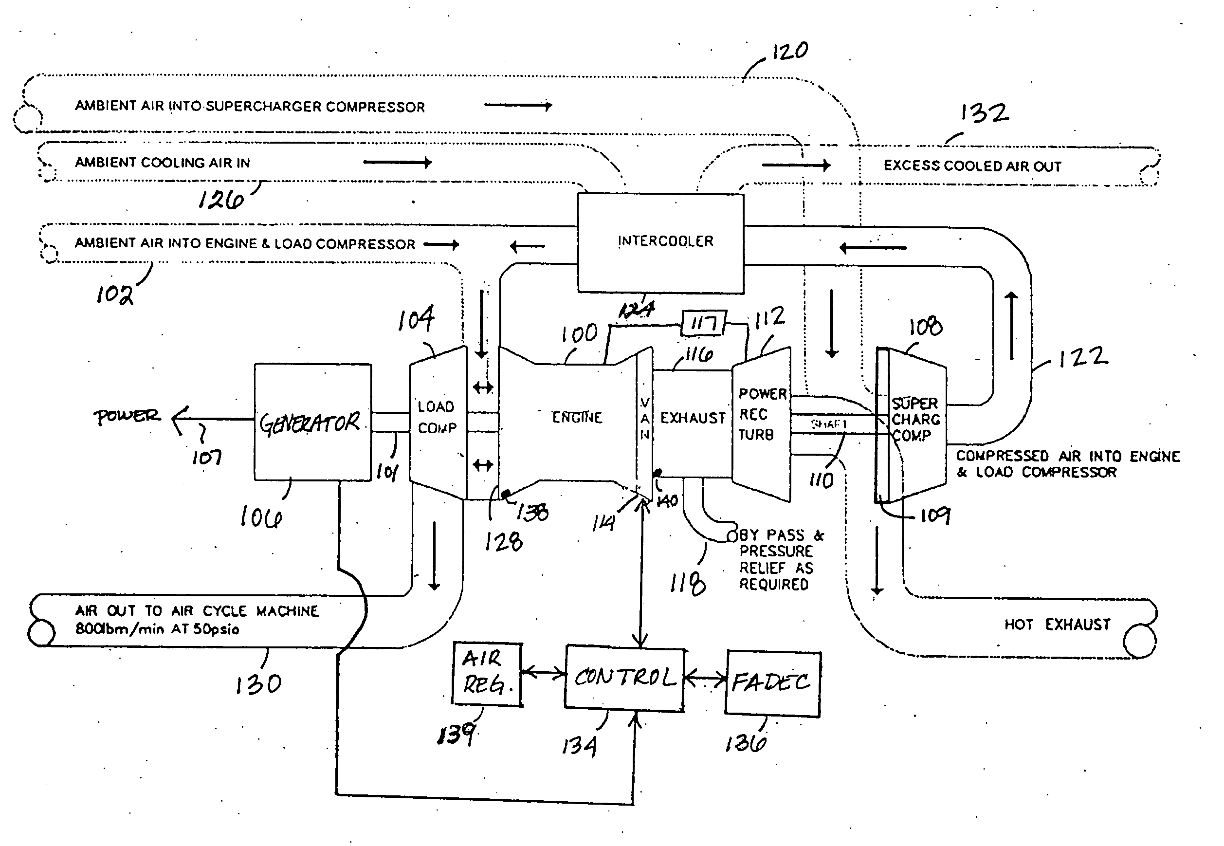
[0018] The detailed description set forth below in connection with the appended drawings is intended as a description of various embodiments of the teachings herein and is not intended to represent the only embodiments in which the teachings herein may be practiced. The term “exemplary” used throughout this disclosure means “serving as an example, instance, or illustration,” and should not necessarily be construed as preferred or advantageous over other embodiments. The detailed description includes specific details for the purpose of providing a thorough understanding of the teachings. However, it will be apparent to those skilled in the art that the teachings herein may be practiced without these specific details. In some instances, well-known structures and devices are shown in block diagram form in order to avoid obscuring the concepts of the teachings herein. Acronyms and other descriptive terminology may be used merely for convenience and clarity and are not intended to limit ...


PUM


Abstract

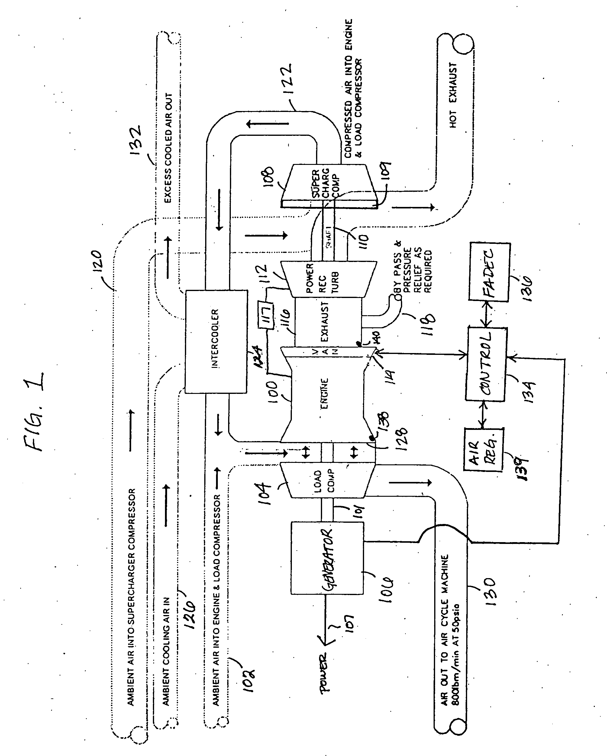
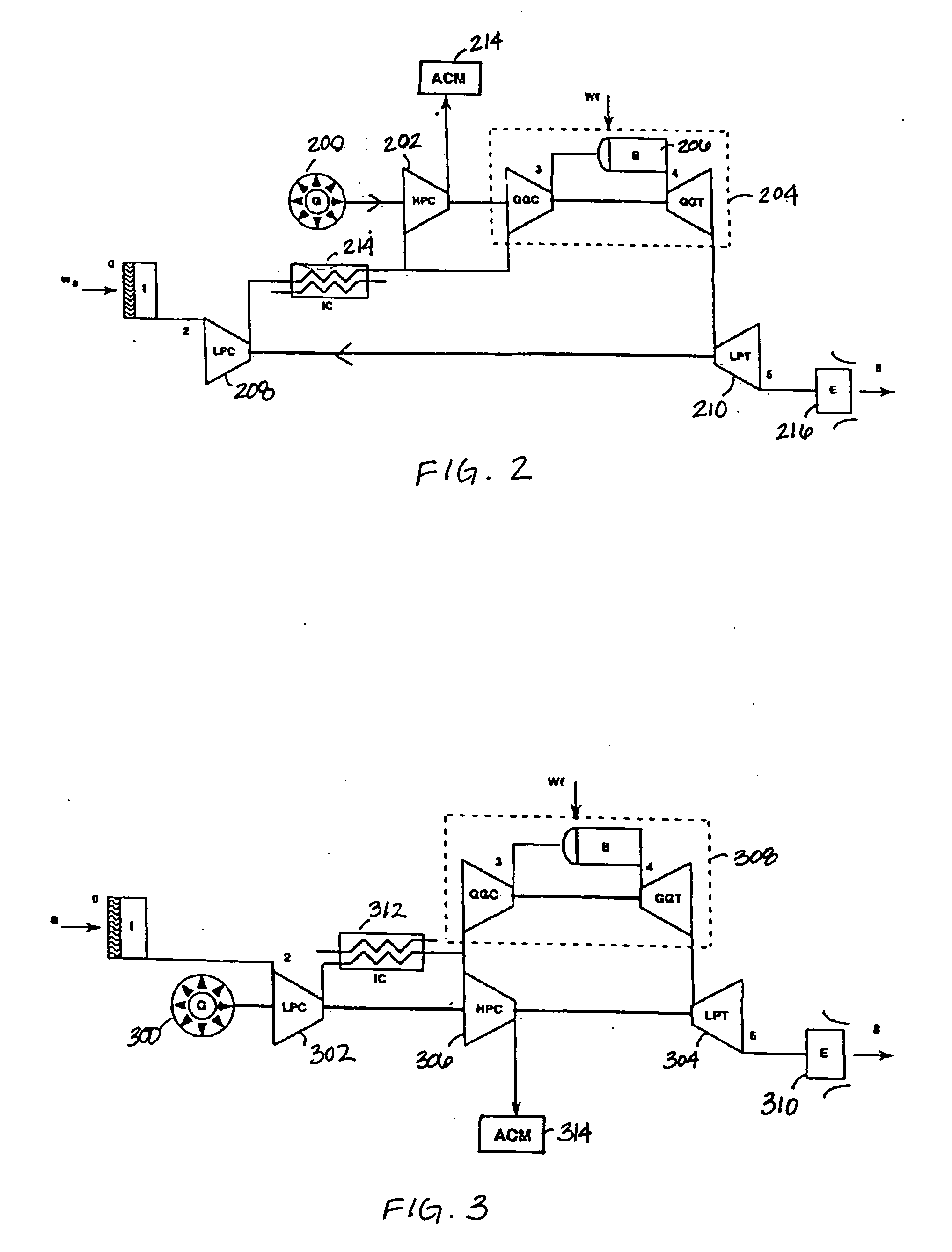
Systems and methods for supplementing a power system to achieve consistent operation at varying altitudes are disclosed herein. A hybrid power system comprising a single power source driving multiple generators may implement a power recovery turbine to drive a supercharger compressor, which may provide compressed air at increased altitudes. The supplemental power system disclosed herein provides necessary shaft horsepower at high altitudes to drive a generator and produce cooling air.

Description

STATEMENT REGARDING FEDERALLY SPONSORED RESEARCH OR DEVELOPMENT [0001] The U.S. Government has a paid-up license in this invention as provided for by the terms of contract No. F33615-03-2367 awarded by USAF / AFMC.BACKGROUND [0002] 1. Field [0003] The present disclosures herein relate to aircraft engines, and more specifically to systems and techniques for augmenting the power capability of aircraft Engines in high altitude environments. [0004] 2. Background [0005] Ongoing development and growth in the area of onboard aircraft electrical systems and electronic sub-systems has resulted in a desire to augment existing aircraft systems with supplemental electrical generating capability. However, standard aircraft production-design characteristics generally leave little, if any, room for significant electrical or cooling air systems expansion or modification. Thus, it is difficult for aircraft to accommodate post-production systems additions. The traditional approach of original equipment...

Claims


Application Information

Patent Timeline
IPC IPC(8): F02C3/04
CPCF02C9/28F02C3/04
Inventor EPSTEIN, STANLEY W.
Owner STEWARD DAVIS INT
Learn More