Electronic deployment system and method for inflating a flotation device

a technology of electronic deployment and flotation device, which is applied in the field of electronic deployment system and flotation device inflator, can solve the problems of operator uncertainty about sensing and deployment, loss of life and property often occurring, and high cost and complexity of mechanical valves

Inactive Publication Date: 2006-01-26
FLOATLOGIC
View PDF5 Cites 13 Cited by
  • Summary
  • Abstract
  • Description
  • Claims
  • Application Information

AI Technical Summary

Benefits of technology

[0013] In addition, the present invention includes a method for inflating a flotation device mounted to a craft. The method comprises electrically activating the flotation device with an electrically operated gas valve using a control system.

Problems solved by technology

This can happen if the hull is breached due to a collision with some object or in heavy waves if the watercraft is swamped.
If the watercraft sinks, a serious condition exists in that loss of life and loss of property often occurs.
Unfortunately, however, flotation devices in the past have used a mechanical float switch valve for determining whether water has entered the watercraft and for deploying the flotation device.
Not only are these mechanical valves oftentimes expensive and complex, prior to leaving the safety of the dock, an operator may want to test the deployment system to determine integrity and reliability.
With mechanical valves, however, difficulty in testing due to their location on the craft and incompatibility with remote diagnostics leaves the operator uncertain whether sensing and deployment are guaranteed.

Method used


Image

  • Electronic deployment system and method for inflating a flotation device
  • Electronic deployment system and method for inflating a flotation device
  • Electronic deployment system and method for inflating a flotation device

Examples


Embodiment Construction

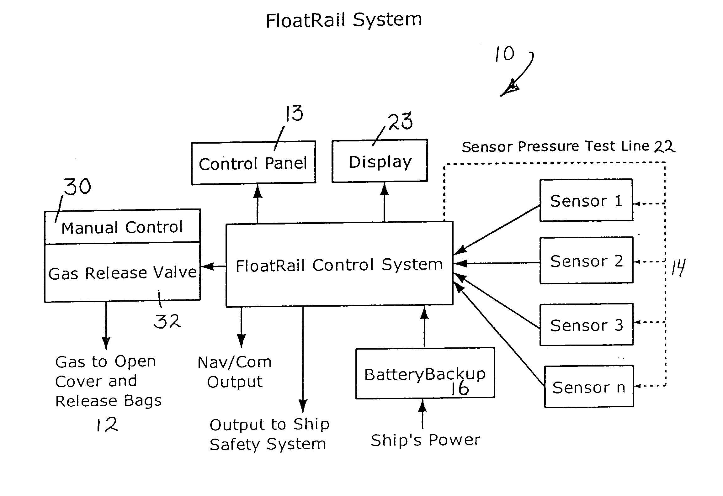
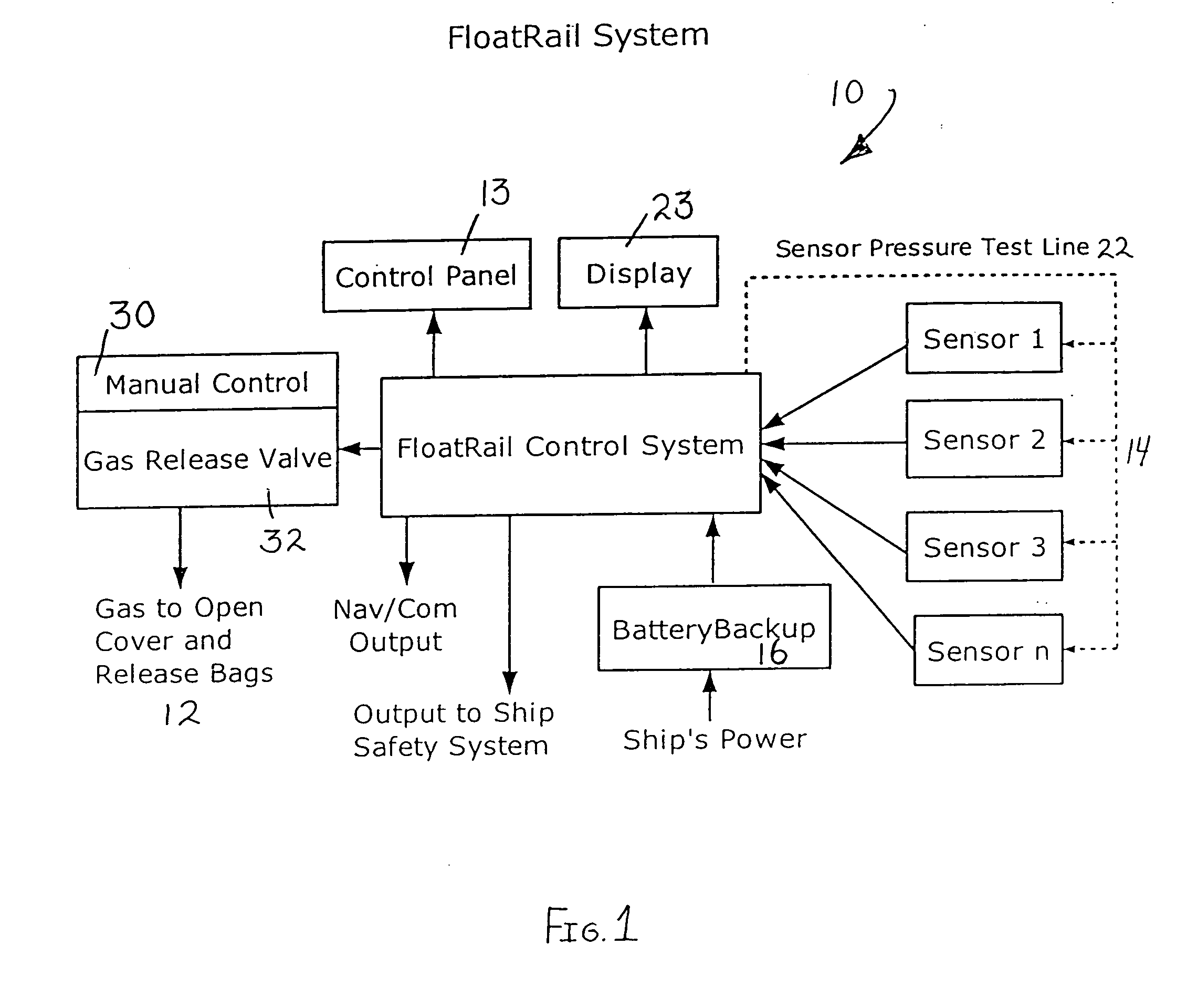
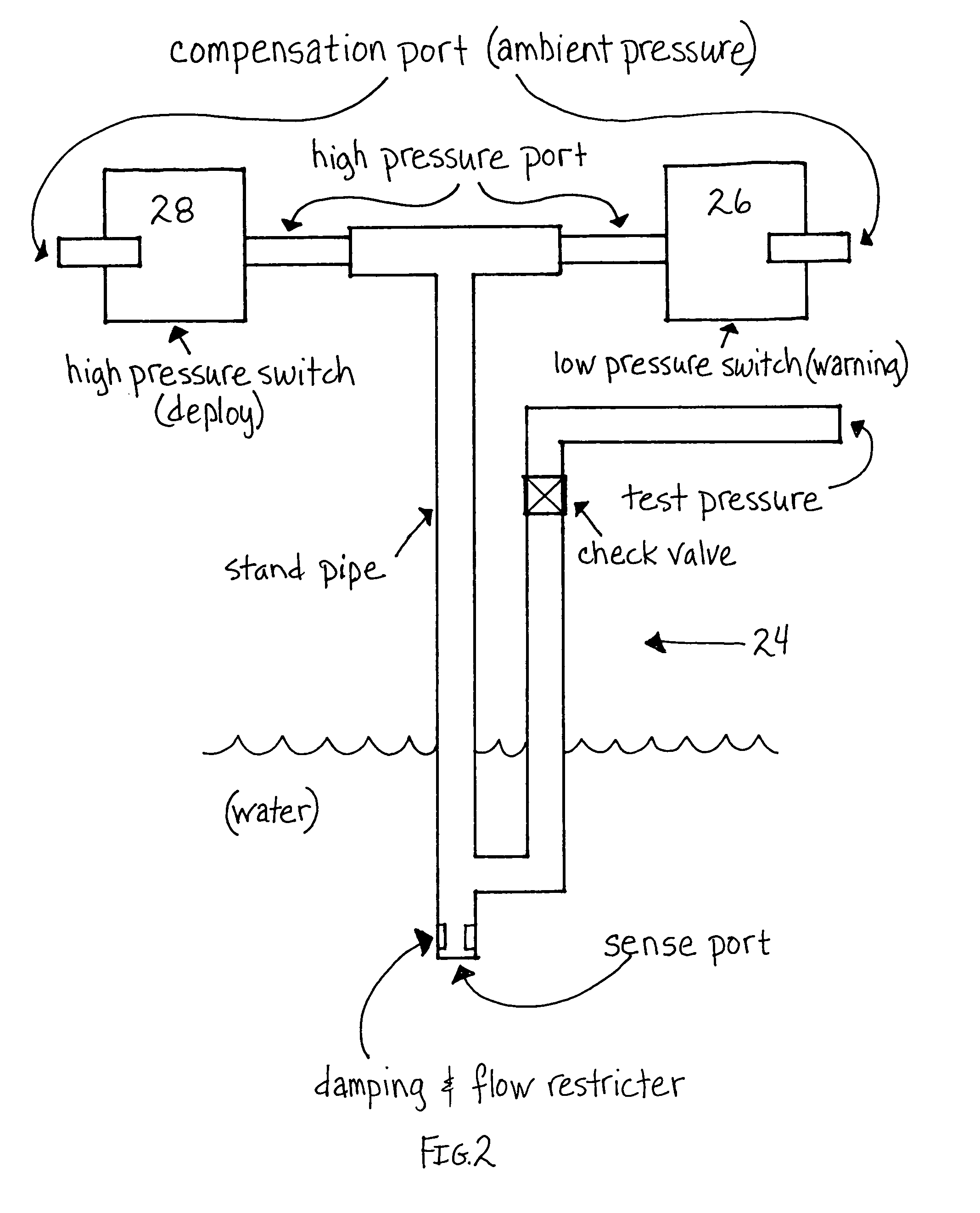
[0023] As illustrated in FIGS. 1-6, the present invention is an electronic deployment system, indicated generally at 10, and a method for activating inflation of at least one flotation device 12 (as best illustrated in FIGS. 3 and 4). The flotation device 12 of the present invention can be any type of flotation device designed and constructed for maintaining a craft (not shown) in a floating and / or stable and / or generally upright condition upon the occurrence of a predetermined event such as flooding, damage, loss of stability or upright condition, and / or high seas.

[0024] Preferably, the flotation device 12 is mounted to the craft and activates, either manually or automatically, to maintain the craft in a floating condition during the occurrence of the predetermined event. The craft can be any type of craft including, but not limited to, pleasure boats, commercial ships, military ships, cruise ships, power boats, row boats, canoes, life boats, rafts, pontoon boats, ski boats, jet s...


PUM


Abstract

An inflatable flotation device mounted to a craft is provided. The device comprises an electronic deployment system for activating inflation of the flotation device. A method for inflating a flotation device mounted to a craft is also provided. The method comprises electrically activating the flotation device with a control system. The present invention further includes a two level switching mechanism providing a first alert level and a second alert level prior to deployment of the flotation device.

Description

[0001] The present application is a continuation of pending provisional patent application Ser. No. 60 / 514,358, filed on Oct. 24, 2003, entitled “Inflating Watercraft Flotation Device”.BACKGROUND OF THE INVENTION [0002] 1. Field of the Invention [0003] The present invention relates to a system and method for inflating a flotation device and, more particularly, it relates to an electronic deployment system and method for inflating a flotation device providing sensor self-testing for system integrity and multiple sensor algorithms for mapping defective sensors. [0004] 2. Description of the Prior Art [0005] Boating is both a popular pastime and a vital commercial activity in much of the world today. A watercraft is often a substantial investment for the owner and / or operator. In the case of commercial boats, the boat is often the livelihood of the owner of the watercraft. As a general concept, watercrafts sink when the hull of the watercraft takes on water and the watercraft loses its ...

Claims


Application Information

Patent Timeline
Patent Type & Authority Applications(United States)
IPC IPC(8): B63B43/02B60CB63B43/12B63B43/14
CPCB63B43/14B63B43/12
Inventor BRAITBERG, MICHAEL
Owner FLOATLOGIC
Why Eureka
Try Eureka