Open hole expandable patch

a patch and expansion technology, applied in the field of open-hole expansion patches, can solve the problems of contaminating production formations, loss of fluids, and undesired drilling of mud and other fluids

Active Publication Date: 2006-01-26
BAKER HUGHES INC
View PDF8 Cites 32 Cited by
  • Summary
  • Abstract
  • Description
  • Claims
  • Application Information

AI Technical Summary

Benefits of technology

[0012] In another aspect, a method of placing a patch in a wellbore having an internal dimension comprises positioning the patch at a selected location in the wellbore. The patch has a longitudinal body that is radially expandable and an associated anchor that is engageable to a wellbore wall. The anchor is engaged with the wellbore wall in a manner that enables the longitudinal body of the patch to remain at the selected location.
[0013] The patch may be made from any suitable material and in any desired form. It may be a solid metallic member, a metallic longitudinal mesh, or a member made from a composite or hybrid material. The anchor may include one or more radially expandable member which can securely engage with the wellbore wall. The anchor is engaged with the borehole wall in a manner that will cause the longitudinal section to remain in the desired location in the wellbore. The longitudinal member and / or the anchor may be made from a suitable material, such as a rubber or another elastomeric material to provide seal between the wellbore well and the longitudinal member to prevent fluid flow between the formation and the earth formation surrounding the wellbore.

Problems solved by technology

Because the wellbore is not yet lined with a casing, drilling mud and other fluids may undesirably flow into the surrounding earth formations from the wellbore.
This not only results in the loss of fluids, but might contaminate production formations.
In this situation, there is the danger that undesirable fluids, such as water, will migrate from the surrounding earth formation into the borehole.
Running of a drill string, for example, into the wellbore and through the patch will result in torsional and axial forces being imparted to the patch.
However, this operation is time consuming as the cement needs to be given time to set and later cure.
Currently there is not a relatively easy and acceptable method of securing a patch within a wellbore.

Method used


Image

  • Open hole expandable patch
  • Open hole expandable patch
  • Open hole expandable patch

Examples


Embodiment Construction

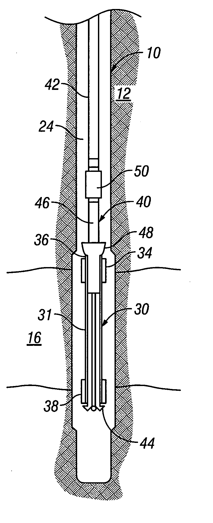
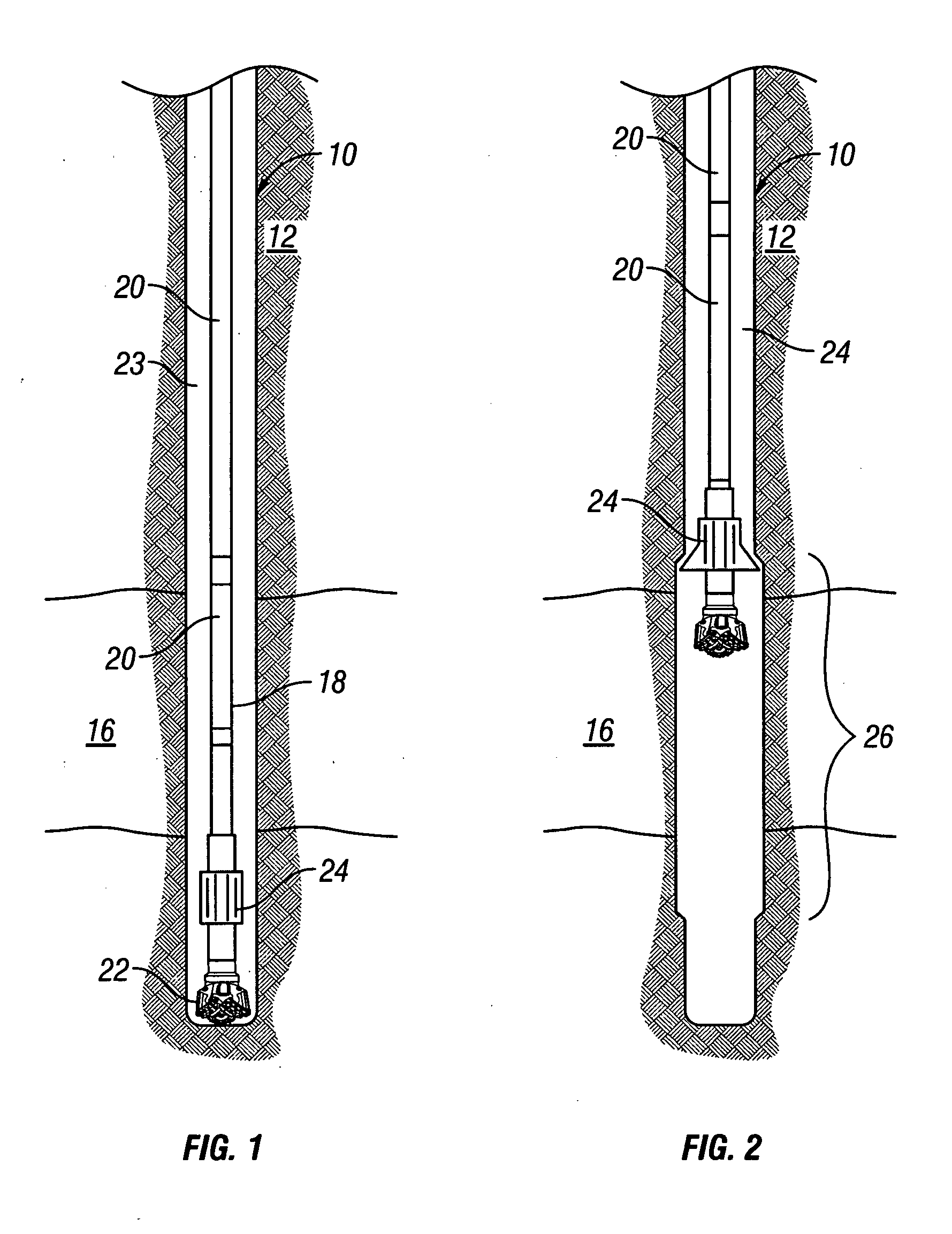
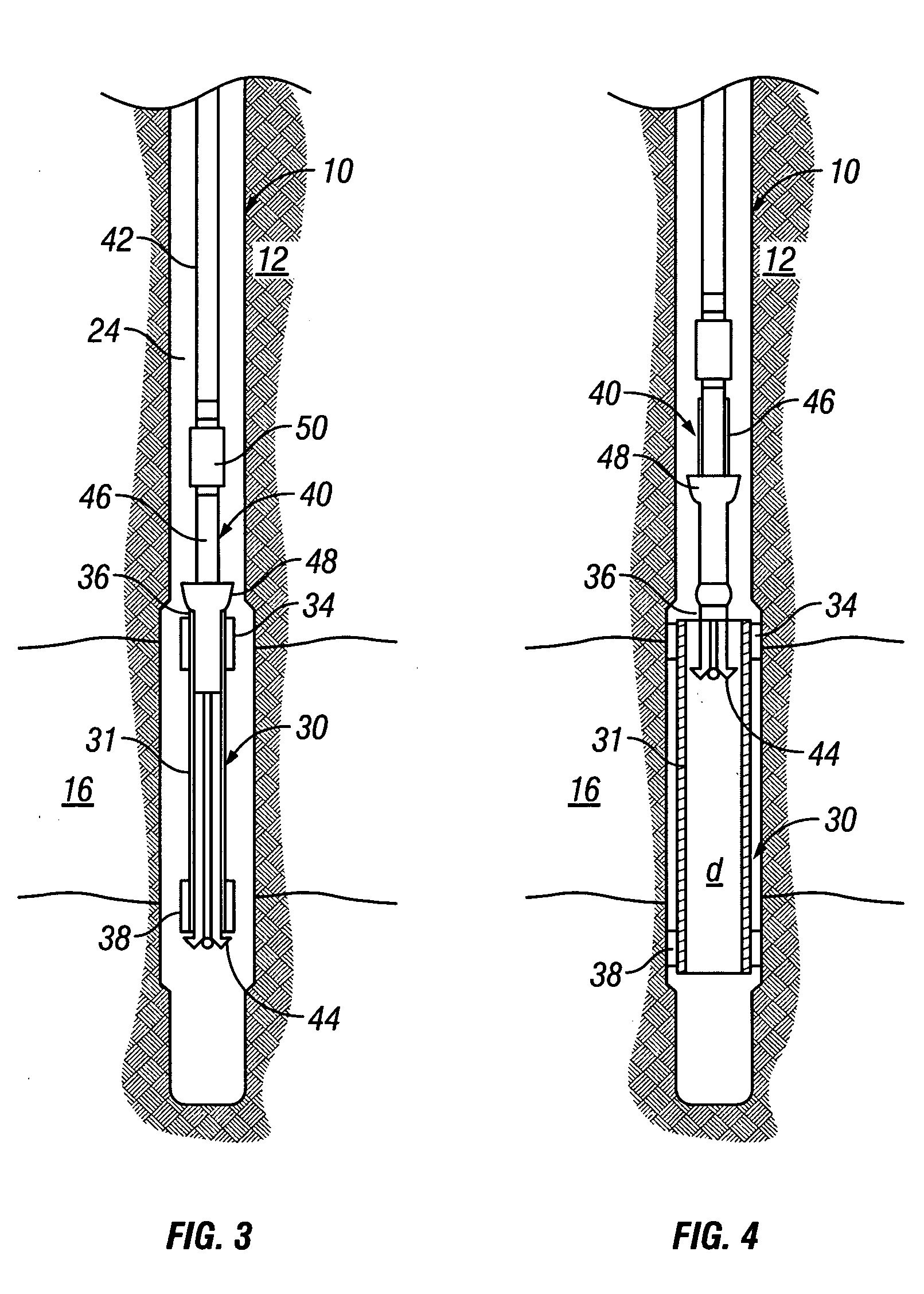
[0036]FIGS. 1-5 depict an exemplary wellbore 10 that has been drilled through the earth 12. The wellbore 10 is an open hole wellbore that lacks casing. The surrounding earth 12 contains a permeable zone 16 into which drilling fluids might flow during the drilling operations. It is desired to seal the zone 16 off from fluid communication with the wellbore 10. FIG. 1 depicts a drill string 18 disposed within the wellbore 10 for initial drilling of the wellbore 10. The drill string 18 includes a tubing that may be made of interconnected drill pipe members 20, and a drill bit 22 at the lower end. As those of skill in the art understand, during drilling, drilling mud (not shown) is pumped down the string of drill pipe members 20, flows out of the drill bit 22 and returns up the annulus 23 to the surface of the wellbore 10. In this situation, it is desired to prevent the drilling mud from escaping into the permeable zone 16 by setting a patch within the wellbore 10. To accomplish this, an...


PUM


Abstract

The invention discloses a patch for placement in a wellbore and associated methods. The patch has a longitudinal member and an anchor that is radially expanded to engage the wall of the borehole to secure the patch against axial and radial movement. The anchor is set using a running tool that radially expands the anchor and the longitudinal body. The anchor may include one or more elements that can be securely engaged within the wellbore. The longitudinal member and/or the anchor may include a sealing element to provide a seal between the wellbore inside and the earth formation surrounding the wellbore.

Description

CROSS-REFERENCE TO RELATED APPLICATIONS [0001] This application claims priority from U.S. Provisional Application Ser. No. 60 / 590,596 filed on Jul. 23, 2004, which is incorporated herein by reference.BACKGROUND OF THE INVENTION [0002] 1. Field of the Invention [0003] This invention relates generally to devices and methods for securing a patch within a wellbore. [0004] 2. Description of the Related Art [0005] Patches are used in uncased wellbores and wellbore sections to prevent collapse of the wellbore and / or preclude unintended fluid flow into or out of the wellbore. A patch is usually a tubular sleeve that is secured to the wall of the wellbore. The patch may be any desired length. The patch provides structural support and fluid sealing. There are two primary scenarios in which it is often desired to use a wellbore patch. [0006] The first scenario occurs during drilling of a wellbore, particularly through unconsolidated earth. Because the wellbore is not yet lined with a casing, d...

Claims


Application Information

Patent Timeline
Patent Type & Authority Applications(United States)
IPC IPC(8): E21B29/00E21B43/10
CPCE21B7/20E21B43/103E21B29/10E21B43/10
Inventor EMERSON, ALAN B.
Owner BAKER HUGHES INC
Why Eureka
Try Eureka