Igniter assembly

a technology of igniter and assembly, which is applied in the direction of vehicle components, pedestrian/occupant safety arrangements, vehicular safety arrangments, etc., can solve the problems of gaps appearing between the igniter and the resin molded body, and achieve the effect of preventing moisture infiltration and ensuring long-term operation reliability

Inactive Publication Date: 2006-01-26
DAICEL CHEM IND LTD
View PDF16 Cites 8 Cited by
  • Summary
  • Abstract
  • Description
  • Claims
  • Application Information

AI Technical Summary

Benefits of technology

[0010] An aspect of the present invention is to provide an igniter assembly which can prevent the infiltration of moisture in the outside air, thereby ensuring long-term operational stability, a manufacturing method for the igniter assembly, and a gas generator for an air bag which uses the igniter assembly.
[0018] However, to integrate the resin sheet and resin molded body more reliably and prevent excessive thermal deformation of the resin sheet, the melting point of the resin used as the resin sheet is preferably equal to or lower than the melting point of the resin used as the resin molded body, and more preferably between 30° C. and 70° C. lower than the melting point of the resin used as the resin molded body.
[0023] In the igniter assembly of the present invention, the resin sheet and resin molded body are integrated with each other such that no gaps exist therebetween, and hence moisture infiltration is prevented. As a result, long-term operational reliability is ensured. Moreover, since the resin sheet and resin molded body are integrated, the resin sheet itself does not become dislodged from the igniter.

Problems solved by technology

However, as described in the “Description of the Related Art” section, during cooling and hardening, volume shrinkage is inevitable, and hence gaps may appear between the igniter and resin molded body.
When the resin molded body is injection-molded to contact the metallic header and conductive pins, and then cooled and hardened, gaps may also appear between these components.

Method used


Image

  • Igniter assembly
  • Igniter assembly
  • Igniter assembly

Examples


Embodiment Construction

(1) Igniter Assembly

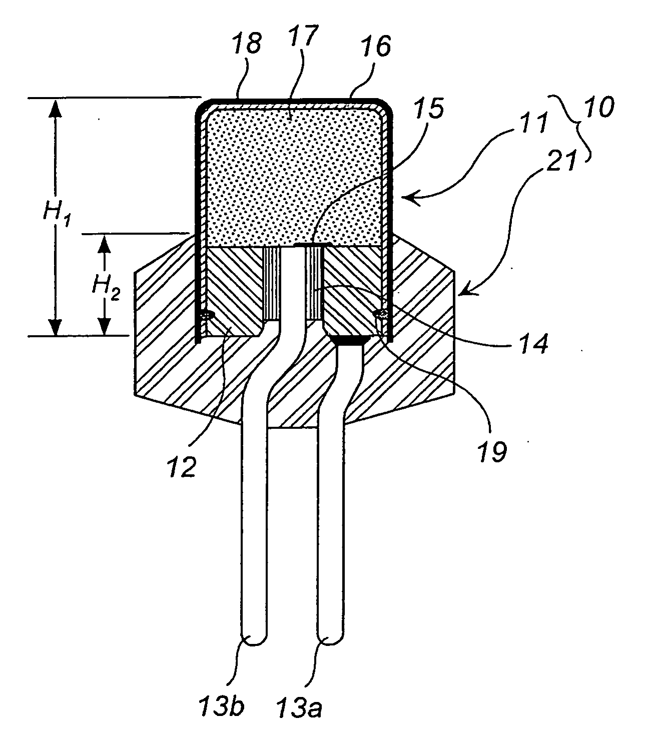
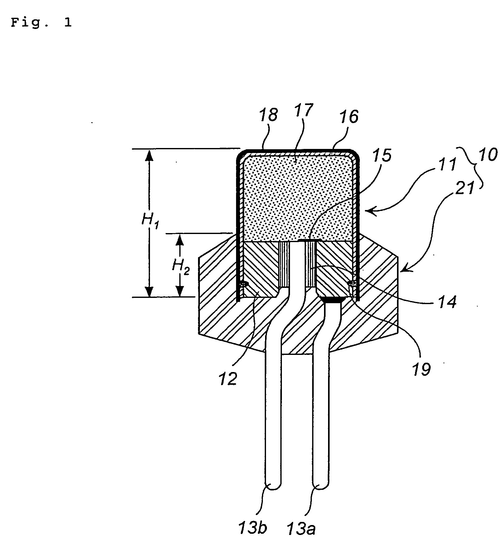
[0027] An igniter assembly will be described using FIG. 1. FIG. 1 is a schematic sectional view in the axial direction of an igniter assembly.

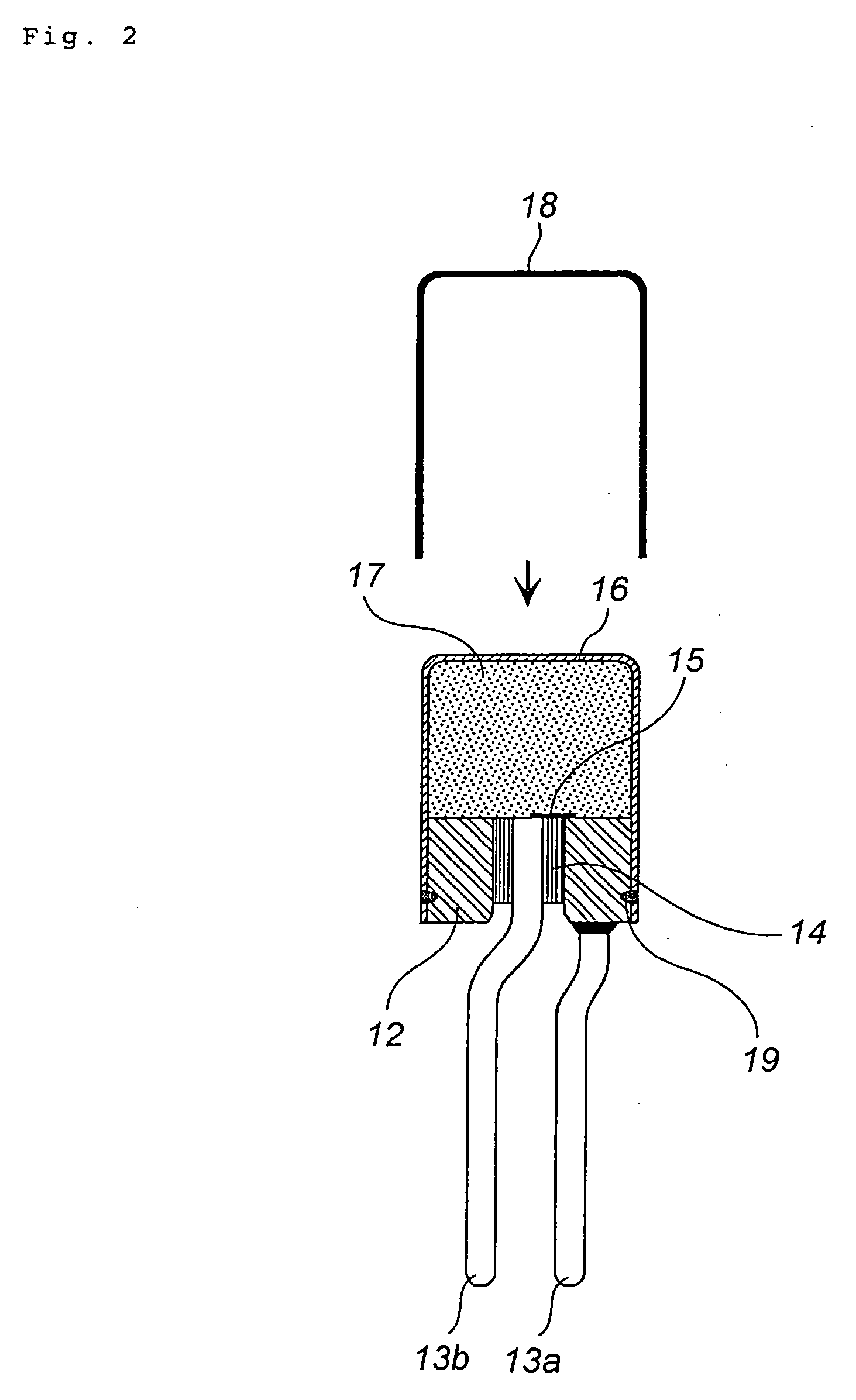
[0028] An igniter assembly 10 comprises an igniter 11 having a metallic header and so on, and a resin molded body 21 surrounding a part of the igniter 11.

[0029] The metallic header 12 holds two conductive pins 13a, 13b. The end portion of the conductive pin 13a is fixed to the metallic header 12, and the end portion of the conductive pin 13b is buried within and fixed to an insulation portion (glass portion) 14 attached integrally to the metallic header 12.

[0030] A heat generating body 15 is provided on the surface of the metallic header 12. One end of the heat generating body 15 contacts the conductive pin 13b, and, bridging the glass portion 14, the other end contacts the surface of the metallic header 12. A metal coil or metal wire which generates heat easily, such as a nichrome wire, for example, may be used as the...


PUM


Abstract

The present invention provides an igniter assembly which is capable of preventing the infiltration of moisture, thus enabling long-term operational reliability. The periphery of a metallic cup 16 charged with an ignition charge 17 is covered by a resin sheet 18. A lower end portion of the resin sheet 18 and a resin molded body 21 are integrated at a contact portion therebetween to prevent the infiltration of moisture. The resin sheet 18 and resin molded body 21 integrated during the manufacturing process by cooling and hardening the resin molded body 21 and resin sheet 18 in a fused state.

Description

[0001] This nonprovisional application claims priority under 35 U.S.C. §119(e) on U.S. Provisional Application No. 60 / 591,877 filed on Jul. 29, 2004 and under U.S.C. §119(a) on Patent Application No. 2004-217039 filed in Japan on Jul. 26, 2004, which are herein incorporated by reference.BACKGROUND OF THE INVENTION [0002] 1. Field of the Invention [0003] The present invention relates to an igniter assembly, a gas generator for an air bag which uses this igniter assembly, and a manufacturing method for the igniter assembly. [0004] 2. Description of the Related Art [0005] When attaching an electric igniter to a gas generator for an air bag, a method of embedding the igniter into a metallic collar and then attaching the igniter to the gas generator in this state is typically employed. To provide insulation in this case, an igniter assembly, in which the periphery of the igniter is wrapped in an insulation sheet, is fitted together with the metallic collar. [0006] This type of igniter as...

Claims


Application Information

Patent Timeline
Patent Type & Authority Applications(United States)
IPC IPC(8): B60R21/26
CPCB60R2021/26029B60R21/26
Inventor KURODA, TAKAOODA, SHINGOYANO, SHIGEAKI
Owner DAICEL CHEM IND LTD
Why Eureka
Try Eureka