Optical scanner

a technology of optical scanners and optical filters, applied in the field of optical scanners, can solve the problems of loss of drive efficiency, difficult to achieve the high resonant frequency sought for many technical applications, and inability to sustain operation at frequencies, etc., and achieve the effect of enhancing flux through the first circui

Inactive Publication Date: 2006-01-26
LOEBEL NICOLAS G +3
View PDF4 Cites 4 Cited by
  • Summary
  • Abstract
  • Description
  • Claims
  • Application Information

AI Technical Summary

Benefits of technology

[0009] The present invention also provides a method for oscillating a flexure element of an optical scanner comprising: using a magnet disposed between two stators and beneath the flexure element to create a first and second magnetic circuits that are generally symmetric and coplanar to one another, wherein a portion of the circuits share a common magnetic path through the magnet and remaining, non-common paths of the circuits through the stators are counter-directional relative to each other; applying electromagnetic flux to one or both of the circuits via stator electrical coils thereby enhancing flux through the first circuit while impeding flux through the second circuit and keeping the stator-induced flux vector through the magnet unchanged; and reversing polarity of said the stator-induced electromagnetic flux at a regular frequency in order to oscillate the flexure element.

Problems solved by technology

While optical resonant scanners are known, in general, they are not capable of sustained operation at frequencies significantly above 10 kHz, especially when large aperture mirrors, high scan angles and / or mirrors composed of thick material (to retain dynamic flatness) are involved.
High rotational inertia thereby makes it difficult to attain the high resonant frequencies sought for many technical applications.
These long flux pathways provide substantial opportunities for eddy current generation and loss of drive efficiency via heating of the ferromagnetic material.

Method used


Image

  • Optical scanner
  • Optical scanner
  • Optical scanner

Examples


Embodiment Construction

The Scanner

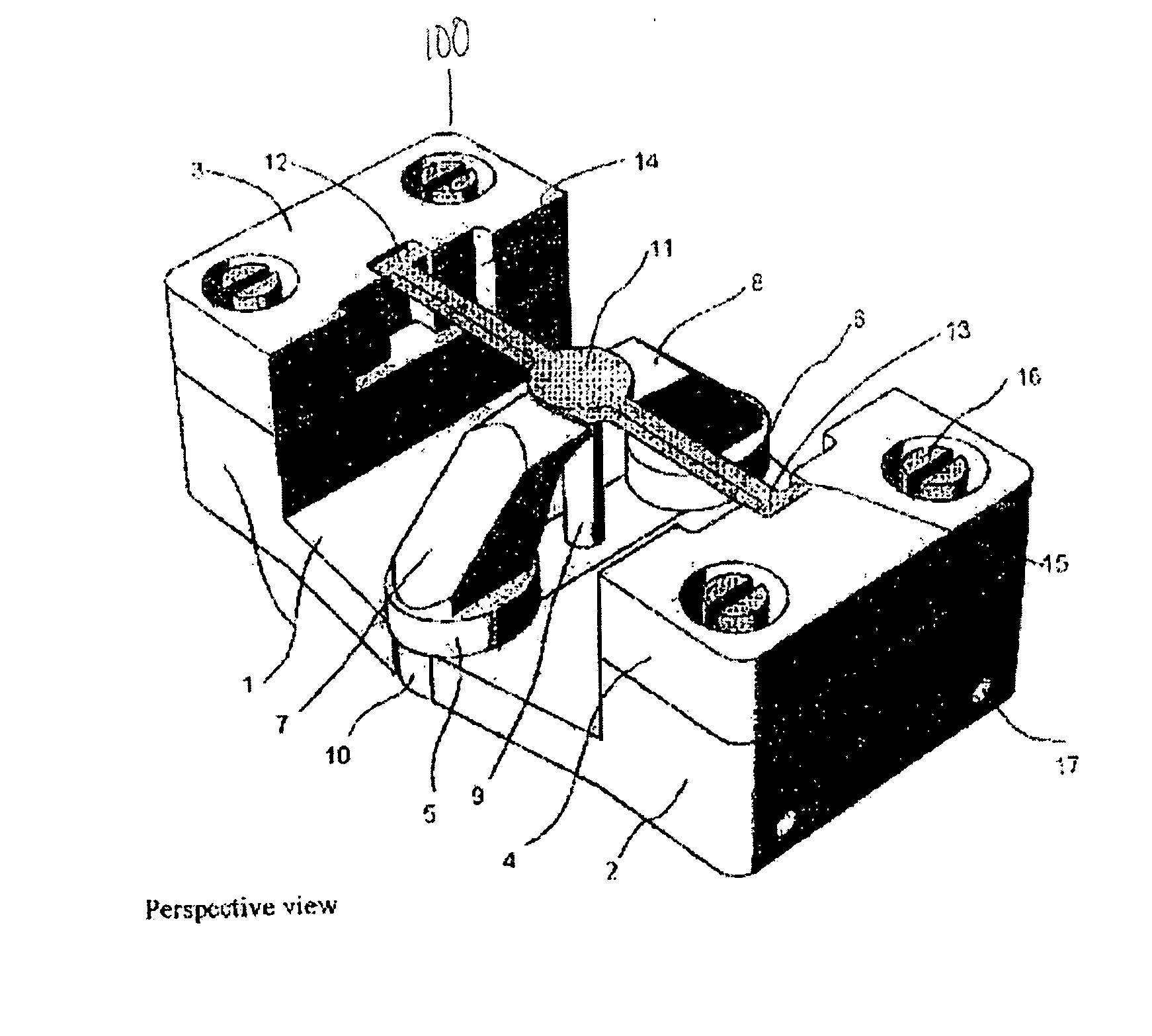
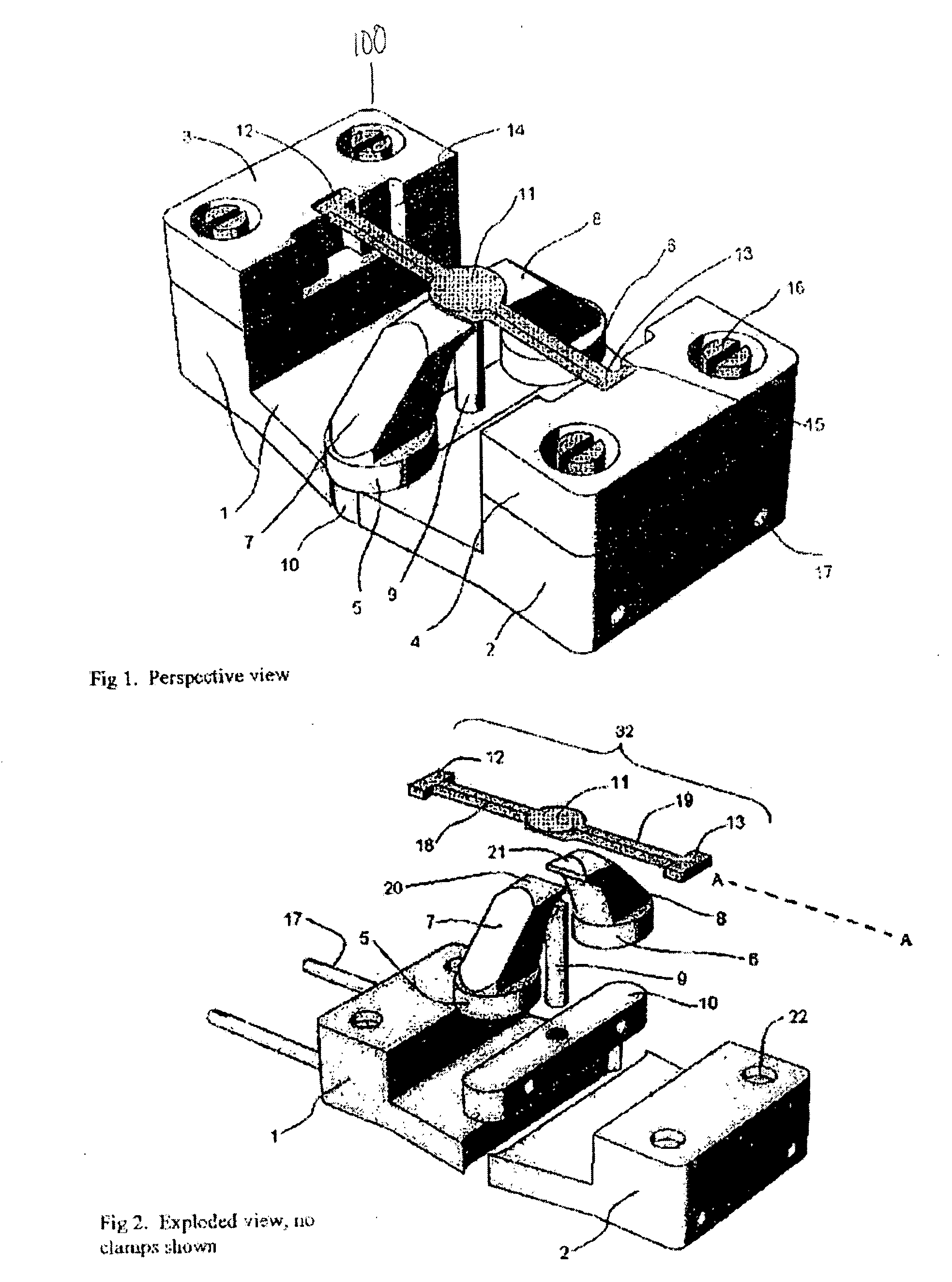
[0015] The resonant optical scanner of the present invention 100 is illustrated in FIGS. 1-4. Referring to FIGS. 1-2, the scanner includes base plates 1, 2 which are connected together via art-disclosed means (e.g., the bolts 17 shown in FIG. 2) to provide mechanical supports for the scanner 100. Mounted on opposite ends of the base plates 1, 2 are end mounts 3, 4. The end mounts are also connected to the base plates 1, 2 via art-disclosed means (e.g., screws 16 and recesses 22 shown in FIGS. 1-2). Alternatively, the base plates 1, 2 and the end mounts 3, 4 can be integrally formed in one piece or two pieces of materials (i.e., base plate 1 and end mount 3 forming a single piece while base plate 2 and end mount 4 forming another piece).

[0016] Referring to FIG. 2, the scanner 100 includes a flexure 32 that is connected to the end mounts 3, 4. The flexure includes a flexure element 11 that is magnetic and serves as the rotating or oscillating element of the scanner 100. ...


PUM


Abstract

An optical scanner comprising stators spaced apart from each other but ferromagnetically coupled together; a magnet positioned relative to the stators such that axis of symmetry of a magnetic field created by the magnet is substantially equidistant from and passes in between ends of the stators; and a flexure element positioned relative to the stators and the magnet such that its center point substantially intersects axis of symmetry of the magnet's magnetic field, wherein the flexure element is not in physical contact with either the stators or the magnet. A method for oscillating an optical scanner's flexure element comprising using a magnet disposed between two stators and beneath the flexure element to create two magnetic circuits that are generally symmetric and coplanar with one another, wherein a portion of the circuits share a common magnetic path through the magnet and remaining, non-common paths of the circuits through the stators are counter-directional relative to each other; applying electromagnetic flux to such circuits via stator electrical coils enhancing flux through one circuit while impeding flux through the other circuit and keeping the stator-induced flux vector through the magnet unchanged; and reversing polarity of the stator-induced electromagnetic flux at a regular frequency in order to oscillate the flexure element.

Description

CLAIM OF BENEFIT OF FILING DATE [0001] The present application claims the benefit of the filing date of U.S. Provisional Application Ser. No. 60 / 583,959, filed on Jun. 29, 2004, and hereby incorporated in its entirety by reference.TECHNICAL FIELD [0002] The present invention is directed to an optical scanner having both stationary magnets and stationary drive coils. BACKGROUND OF THE INVENTION [0003] While optical resonant scanners are known, in general, they are not capable of sustained operation at frequencies significantly above 10 kHz, especially when large aperture mirrors, high scan angles and / or mirrors composed of thick material (to retain dynamic flatness) are involved. Most known resonant scanners that are magnetically driven include either moving magnets or moving coils as components of an electromagnetic circuit for generating and maintaining oscillatory motion of a flexure element. Many of these scanners have a high rotational inertia associated with the flexure element...

Claims


Application Information

Patent Timeline
Patent Type & Authority Applications(United States)
IPC IPC(8): H02K33/00G02B26/08G02B7/182G02B26/10
CPCG02B7/1821G02B26/10H02K33/16H02K33/12G02B26/105
Inventor LOEBEL, NICOLAS G.ROSE, ANDREASGITLIN, MARKMELVILLE, DAVID
Owner LOEBEL NICOLAS G
Why Eureka
Try Eureka