Liquid crystal display device

a liquid crystal display and display device technology, applied in static indicating devices, non-linear optics, instruments, etc., can solve the problems of low utilization efficiency of r, g and b light components, upset visual white balance, etc., and achieve favorable white balance

Inactive Publication Date: 2006-01-26
ALPS ALPINE CO LTD
View PDF12 Cites 3 Cited by
  • Summary
  • Abstract
  • Description
  • Claims
  • Application Information

AI Technical Summary

Benefits of technology

[0019] According to this configuration, the gray-scale display can be performed, even when the vo

Problems solved by technology

In such a configuration using the color filters, however, since three subpixels of R, G, and B constitute one set, utilization efficiency of each of R, G, and B light components is low.
However, since the R, G, and B ligh

Method used


Image

  • Liquid crystal display device
  • Liquid crystal display device
  • Liquid crystal display device

Examples


Embodiment Construction

[0025] An embodiment of the present invention will now be described with reference to the accompanying drawings.

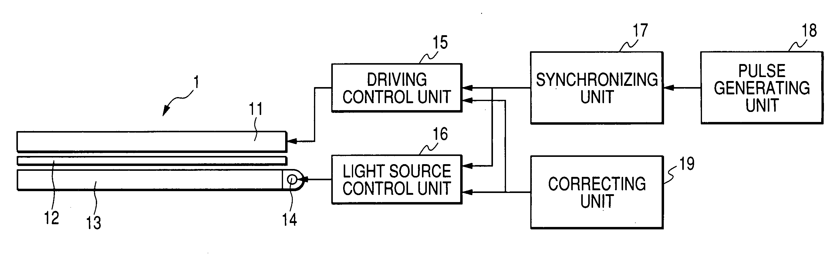
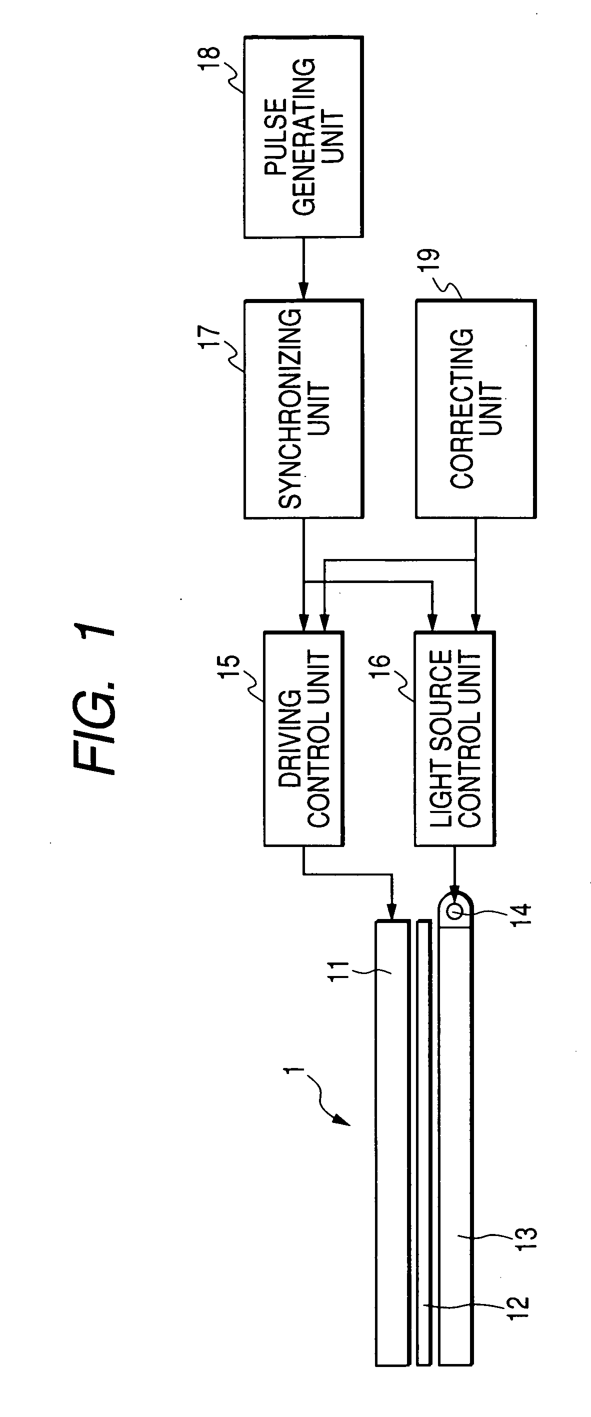
[0026]FIG. 1 is a diagram schematically showing the configuration of a liquid crystal display device according to an embodiment of the present invention. The liquid crystal display device 1 primarily includes a liquid crystal display panel 11 that performs various kinds of display, a plurality of light sources 14, a light guiding plate 13 that reflects and propagates light components from the plurality of light sources 14 to be emitted toward the liquid crystal display panel, a light diffusing plate 12 that diffuses the light components emitted from the light guiding plate 13, a driving control unit 15 that controls display on the liquid crystal display panel 11, a light source control unit 16 that controls luminescence of the plurality of light sources 14, a synchronizing unit 17 that synchronizes the display on the liquid crystal display panel 11 and the luminescence of...


PUM


Abstract

In a liquid crystal display device, in the vicinity of one end surface of a light guiding plate, a plurality of light sources are disposed. On a main surface of the light guiding plate facing a liquid crystal display panel, a light diffusing plate is disposed. On the light diffusing plate, the liquid crystal display panel is disposed. The liquid crystal display device includes a driving control unit that controls display of the liquid crystal display panel, a light source control unit that controls luminescence of the plurality of light sources, a synchronizing unit that synchronizes display of the liquid crystal display panel and the luminescence of the plurality of light sources, a pulse generating unit that generates pulses for driving the liquid crystal display panel or the plurality of light sources, and a correcting unit that corrects control parameters in the driving control unit and the light source control unit.

Description

BACKGROUND OF THE INVENTION [0001] 1. Field of the Invention [0002] The present invention relates to a liquid crystal display device, and more particularly, to a liquid crystal display device using a field sequential method. [0003] 2. Description of the Related Art [0004] The related art color liquid crystal display devices has a configuration in which liquid crystal cells, each serving as an optical shutter, and color filters of R, G, and B provided in respective pixels of the liquid crystal cells are combined. In this configuration, transmittance of each pixel is separately controlled so as to display an arbitrary color. In such a configuration using the color filters, however, since three subpixels of R, G, and B constitute one set, utilization efficiency of each of R, G, and B light components is low. Further, driving circuits for the subpixels three times as much as the number of pixels must be provided. [0005] Therefore, a field sequential method has been used in which the R, ...

Claims


Application Information

Patent Timeline
IPC IPC(8): G09G3/36
CPCG09G3/3413G09G2310/0235G09G2320/0666G09G2320/0646G09G2320/0285G02F1/133
Inventor OIZUMI, MITSUOHAYASHI, YUZO
Owner ALPS ALPINE CO LTD
Why Eureka
Try Eureka