Touch panel input device

a technology of input device and touch panel, which is applied in the direction of instruments, computing, electric digital data processing, etc., can solve the problems of insufficient warping, inability to accurately determine whether the input operation of the touch panel is correct, and inability to reliably vibrate the touch panel, so as to prevent the degradation reliably vibrate, and prevent the piezoelectric constant of the piezoelectric substrate from dropping.

Inactive Publication Date: 2006-01-26
RICHMOND EEI +1
View PDF0 Cites 21 Cited by
  • Summary
  • Abstract
  • Description
  • Claims
  • Application Information

AI Technical Summary

Benefits of technology

[0018] If the selector switch is used to short the set of drive electrodes of the piezoelectric substrate when the device is not operating, contact by a statically charged conductor with either one of the drive electrodes does not result in the generation of a DC electric field between the drive electrodes, and there is no deterioration of the piezoelectric substrate.
[0020] By having the selector switch perform zero-cross switching of the connections between the pair of drive electrodes and the pair of output terminals, a potential that is double the potential generated by the AC power supply circuit is applied to the set of drive electrodes. Distortion of the piezoelectric substrate is proportional to the electric field, so a predetermined distortion can be generated even if the DC power supply potential is stepped up to a high potential. This makes it possible to provide vibrations with an amplitude that is sufficient for providing a sensation on the touch panel.
[0021] By connecting the set of drive, electrodes to one of the output terminals when the touch panel input device is not being operated, the set of drive electrodes can be shorted and degradation of the piezoelectric substrate can be prevented.
[0022] With the touch panel input device of the present invention, the set of drive electrodes of the piezoelectric substrate can be shorted when the touch panel input device is not operation and is not being used. Thus, the piezoelectric constant of the piezoelectric substrate can be prevented from dropping and when the touch panel input device is being used and an input operation is detected, the drive potential can be applied to the piezoelectric substrate and the touch panel can be reliably vibrated.
[0023] In addition to these advantages, a selector switch can be used to provide a potential at the set of drive electrodes of the piezoelectric substrate that is twice the drive potential generated at the AC power supply circuit. This allows the set of drive electrodes to be shorted easily when the device is not being operated.

Problems solved by technology

The operator can only know the operation results from the processing device, e.g., a personal computer, and is therefore unsure about whether or not the input operation to the touch panel has been acknowledged.
This results in inadequate warping, i.e., vibration in the touch panel 101, even when an AC drive potential is applied.
However, this does not completely solve the problem described above since there is the possibility of a statically charged conductor coming into contact with one of the drive electrodes 120a, 120b of the piezoelectric substrate 120 or with a drive power supply circuit pattern connected to one of the electrodes.

Method used


Image

  • Touch panel input device
  • Touch panel input device
  • Touch panel input device

Examples


Embodiment Construction

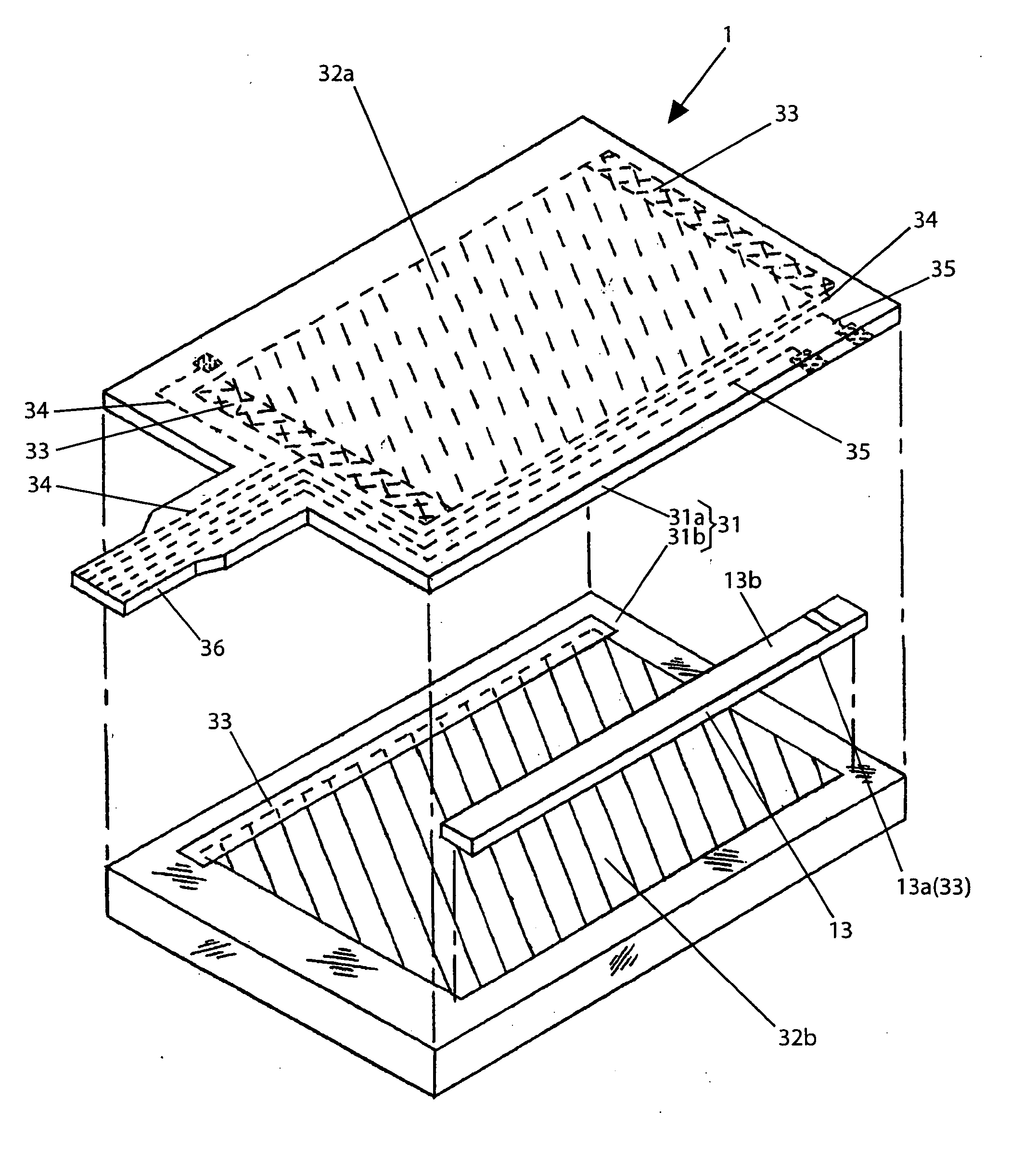
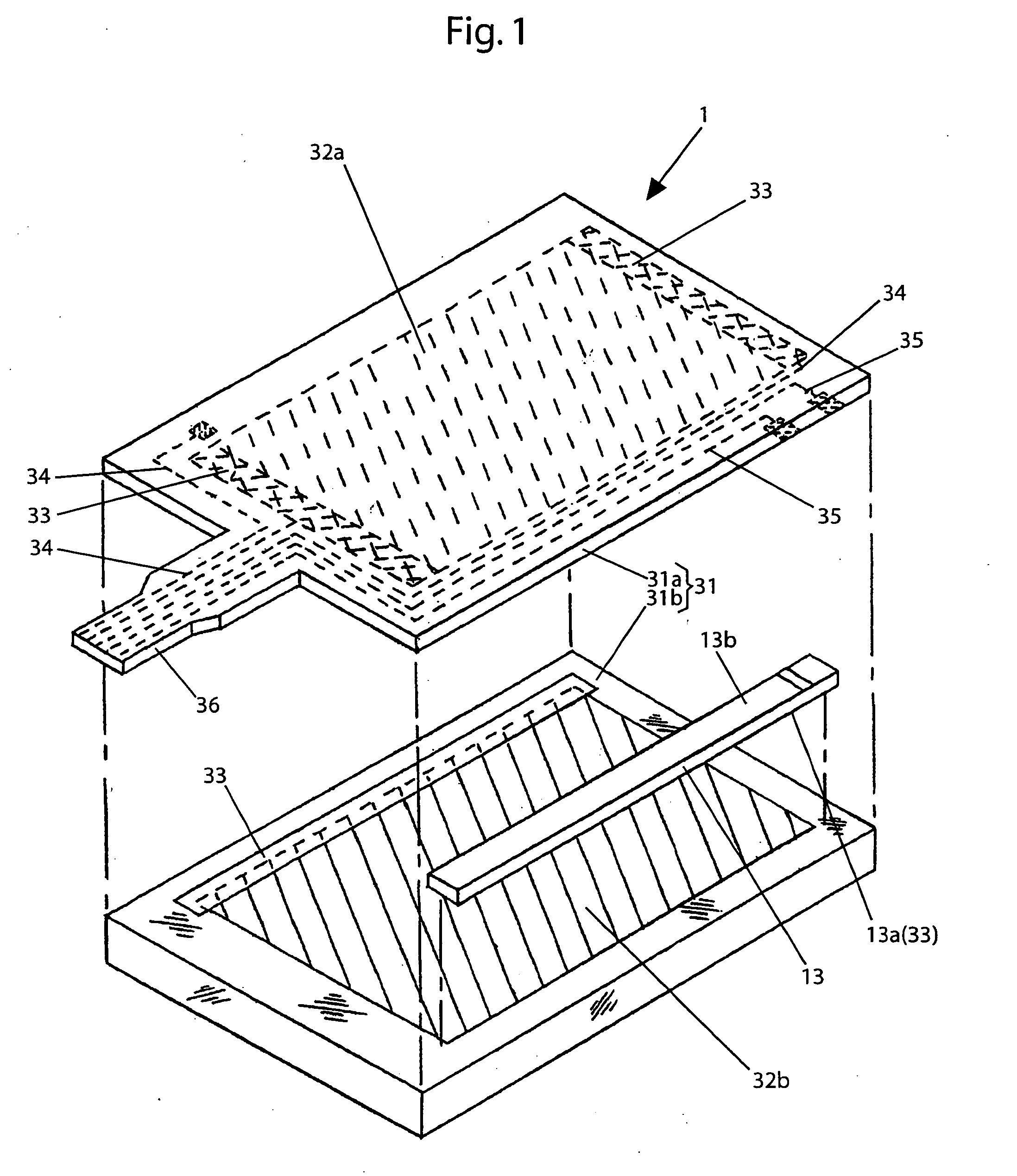
[0037] A touch panel input device 1 according to an embodiment of the present invention will be described, with references to FIGS. 1-4. In the touch panel input device 1 according to this embodiment, a resistance pressure-sensitivity tablet method is used where opposing surfaces of conductive layers are formed as uniform resistor films. The presence and position of an input operation is detected through the contact and contact position of the conductor layers. FIG. 1 is an exploded perspective drawing of the touch panel input device 1 and shows a touch panel 31 formed from a movable plate 31a made from PET (polyethylene terephthalate) and a support substrate 31b made from a glass substrate.

[0038] A movable conductor layer 32a and a fixed conductor layer 32b, which have identical resistances per unit length, are adhered to opposing surfaces of the movable plate 31a and the support substrate 31b. Also, lead-out electrodes 33 for generating a predetermined detection potential to the ...


PUM


Abstract

The present invention provides a touch panel input device that reliably prevents degradation of a piezoelectric substrate. During inactive periods in which a touch panel input device is not used, the connection between a set of output terminals of an AC power supply circuit and a set of associated drive electrodes on the piezoelectric substrate is switched with a selector switch so that the drive electrodes are shorted. During inactive periods, no DC potential is applied to the set of drive electrodes even if a charged conductive body comes into contact with the drive electrodes or a drive power source pattern connected thereto. This makes it possible to prevent the degradation of the piezoelectric substrate.

Description

INCORPORATION BY REFERENCE [0001] The present application claims priority under 35 U.S.C. §119 to Japanese Patent Application No. 2004-217262 filed on Jul. 26, 2004. The content of the application is incorporated herein by reference in its entirety. FIELD OF THE INVENTION [0002] The present invention generally relates to touch panel input devices and more specifically to a touch panel input device that vibrates a touch panel by expanding and contracting a piezoelectric substrate secured to the touch panel and generating an input operation feedback when an input operation is performed. BACKGROUND OF THE INVENTION [0003] In a touch panel input device, also known as a digitizer, an input operation is performed by using a stylus pen or finger to apply pressure in an operation area set up on the touch panel. The position in the operation area of the input operation is detected and input position data is output to a processing device, e.g., a personal computer, indicating the input operat...

Claims


Application Information

Patent Timeline
Patent Type & Authority Applications(United States)
IPC IPC(8): G09G5/00
CPCG06F3/016G06F3/045G06F3/0416
Inventor YOSHIKAWA, OSAMU
Owner RICHMOND EEI
Why Eureka
Try Eureka