Seal ring and ink cartridge using thereof
a technology of sealing rings and ink cartridges, applied in printing and other directions, can solve the problems of contaminating the surroundings, ink leakage through the aperture, dirty workers' clothes,
- Summary
- Abstract
- Description
- Claims
- Application Information
AI Technical Summary
Benefits of technology
Problems solved by technology
Method used
Image

Examples
embodiment 1
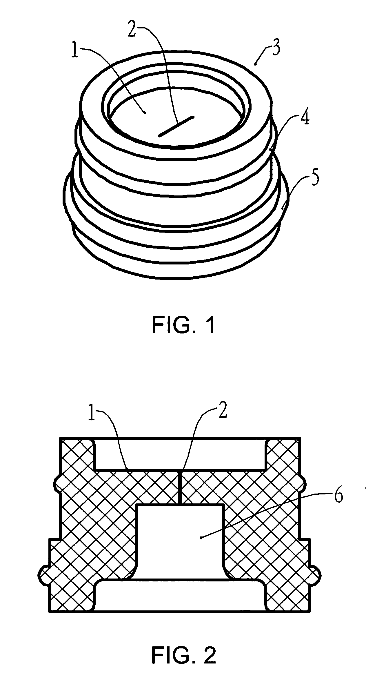
[0031] As shown in FIG. 1, the seal ring is a tube-shaped, elastic part. On an outer wall, there are raised ring structures 4 and 5 which are used to connect with and seal the inner wall of an ink cartridge outlet. On the top of the seal ring, there is a sealing film 1, which includes a crack 2 therein.
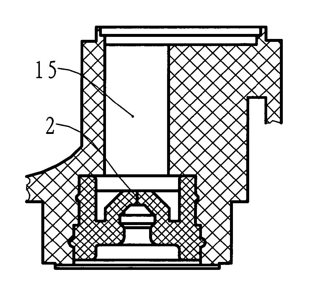
[0032]FIG. 2 is a sectional view of the seal ring along the vertical direction of the crack 2. As shown in FIG. 2, there is an insertion opening 6 which extends upwardly. The internal diameter of the insertion opening 6 is approximately the same as an external diameter of an ink supply needle. The top sealing film 1 is located on the top of the insertion opening 6. In its natural state, the top of the insertion opening 6 is closed. When the crack 2 opens, the insertion opening 6 connects to a space above the top sealing film 1. The top sealing film 1 has certain thickness that enables the crack 2 to close naturally. The maximum diameter of the space above the top sealing film 1, wher...
embodiment 2
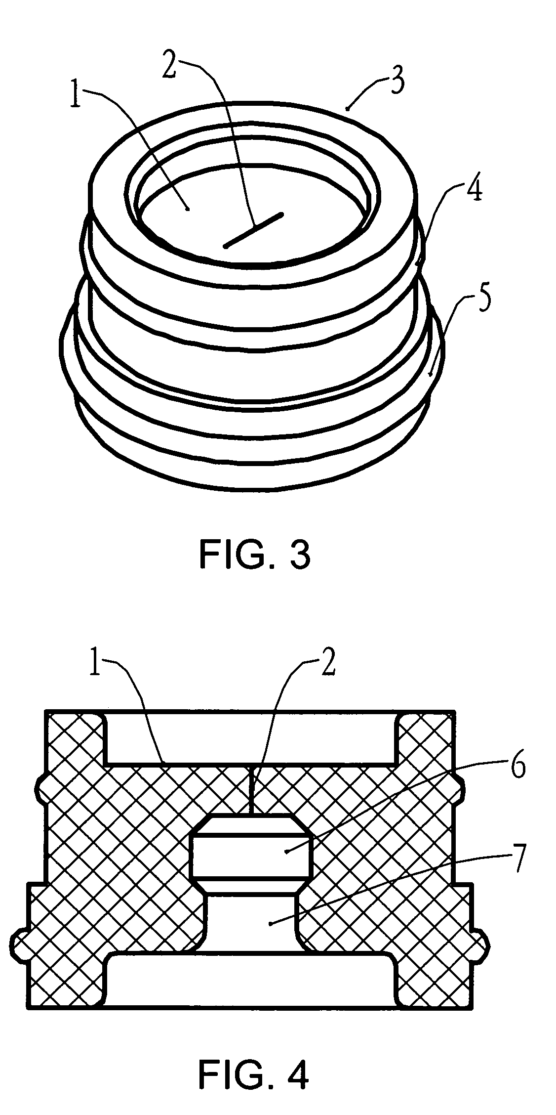
[0033] As shown in FIG. 3, the seal ring of this embodiment looks, from its outside, the same as that of Embodiment 1. The same part numbers in this embodiment denote the same as the previous.
[0034]FIG. 4 is a sectional view of the seal ring along the vertical direction of the crack 2. An insertion opening 6 extends upwardly. In this embodiment, however, the bottom of the insertion opening 6 includes a narrower portion 7. The internal diameter of the insertion opening 6 is approximately the same as the external diameter of ink supply needle, while the internal diameter of the narrower portion 7 is smaller than the external diameter of the ink supply needle. The narrower portion 7 stabilizes and further seals the ink supply needle. Atop sealing film 1 is located on the top of the insertion opening 6. In its natural state, the insertion opening 6 is closed. When the crack 2 opens upon insertion of the ink supply needle, the insertion opening 6 connects to the space above the top seal...
embodiment 3
[0035] As shown in FIG. 5, the seal ring of this embodiment is provided with a support 8 which meets the crack 2 at right angles.
[0036]FIG. 6 is a sectional view of the seal ring along the vertical direction of the crack 2. The top sealing film 1 is approximately semi-spherical in shape. The length of the crack 2 is the same as or slightly smaller than the diameter of the insertion opening 6, i.e., the same as or slightly smaller than the diameter of the ink supply needle. As shown in FIG. 6, the diameter of the narrower portion 7 is smaller than that of the ink supply needle.
PUM
 Abstract
Description
Claims
Application Information
 - R&D
- Intellectual Property
- Life Sciences
- Materials
- Tech Scout
- Unparalleled Data Quality
- Higher Quality Content
- 60% Fewer Hallucinations
Browse by: Latest US Patents, China's latest patents, Technical Efficacy Thesaurus, Application Domain, Technology Topic, Popular Technical Reports.
© 2025 PatSnap. All rights reserved.Legal|Privacy policy|Modern Slavery Act Transparency Statement|Sitemap|About US| Contact US: help@patsnap.com