Jewelry tag substrate

Inactive Publication Date: 2006-01-26
PLUMMER SEAN A
View PDF12 Cites 9 Cited by
  • Summary
  • Abstract
  • Description
  • Claims
  • Application Information

AI Technical Summary

Benefits of technology

[0004] Advantageously, a self-laminating jewelry tag provides a clear laminate that is configured to fold over the label or print area of a jewelry tag so as to protect the printed information from wear, cleaning or other processes that tend to render the printing illegible. The jewelry tag label can be adapted for ink jet, laser or thermal printing.
[0005] Conventional jewelry tags also detract from the appearance of jewelry on display. Retailers go to considerable effort to hide tag labels in display cases. The portion of the tag that attaches to the jewelry, however, is difficult to cover-up. Advantageously, one embodiment of a clear jewelry tag has a clear shank that reduces tag visibility. In another embodiment, the entire jewelry tag is c

Problems solved by technology

As a result, printing on conventional jewelry tags is often degraded or removed entirely due to ordinary wear.
Further, there are currently no laser or inkjet printable jewelry tags on the market where the printing will not be degraded by an ultrasonic or steam cleaning process.
Jewelers, however, typically possess laser or inkjet printers

Method used


Image

  • Jewelry tag substrate
  • Jewelry tag substrate
  • Jewelry tag substrate

Examples


embodiment 100

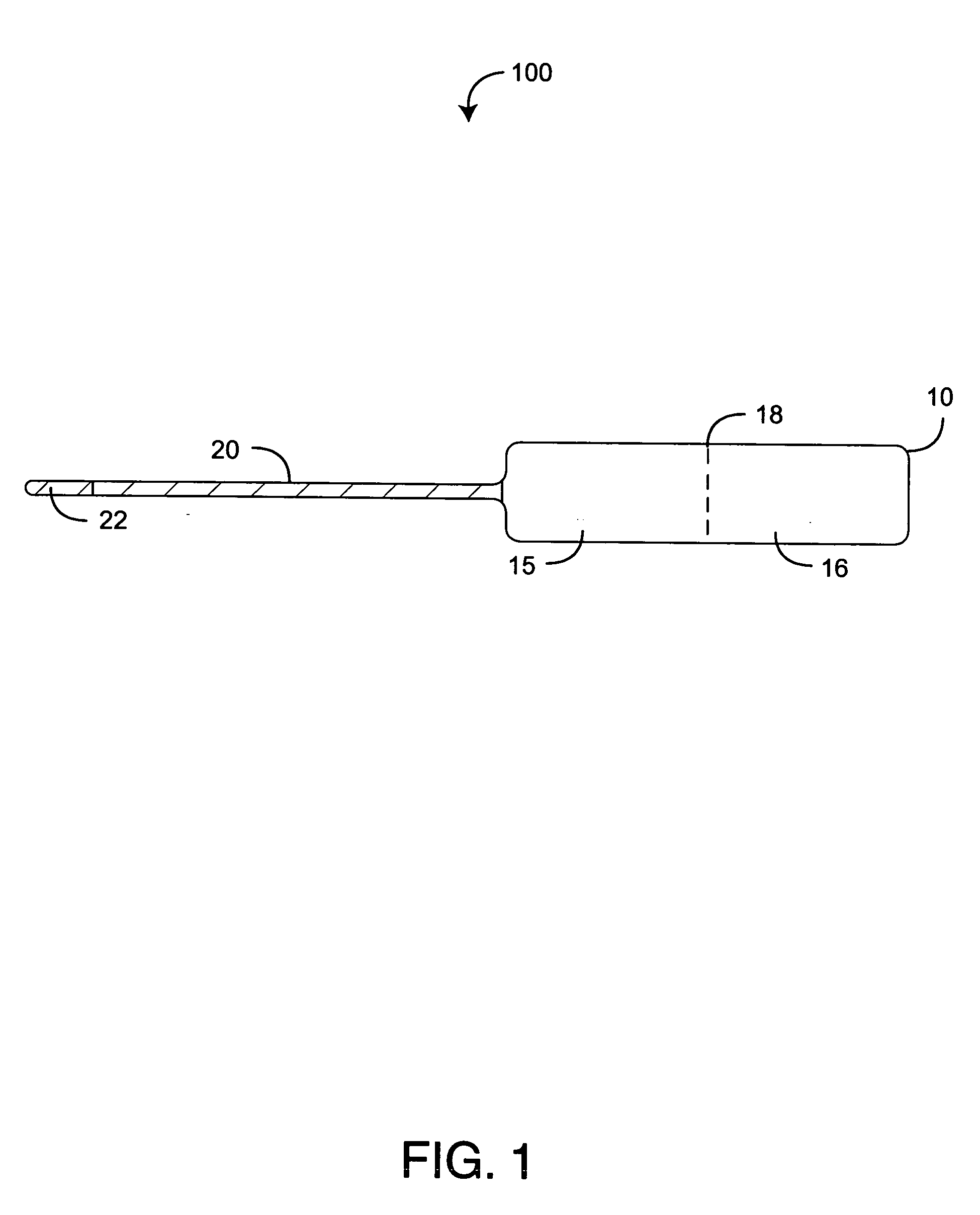
[0021] As shown in FIGS. 1-2, the label 10 extends generally inline with the rat tail shank 20. Further, the rat tail shank 20 and the second section 16 extend from opposite ends of the first section 15, and the label fold line 18 extends generally perpendicular to the shank 20 between the sections 15, 16. In a particular embodiment, the rat tail shank 20 is adhesive free except at the shank tip 22. As shown in FIG. 1, one jewelry tag embodiment 100 has a label 10 that is opaque and a rat tail shank 20 that is clear. As such, printing on the label 10 is readily visible, but the shank 20 is not readily visible when attached to jewelry in a display case, for example.

embodiment 200

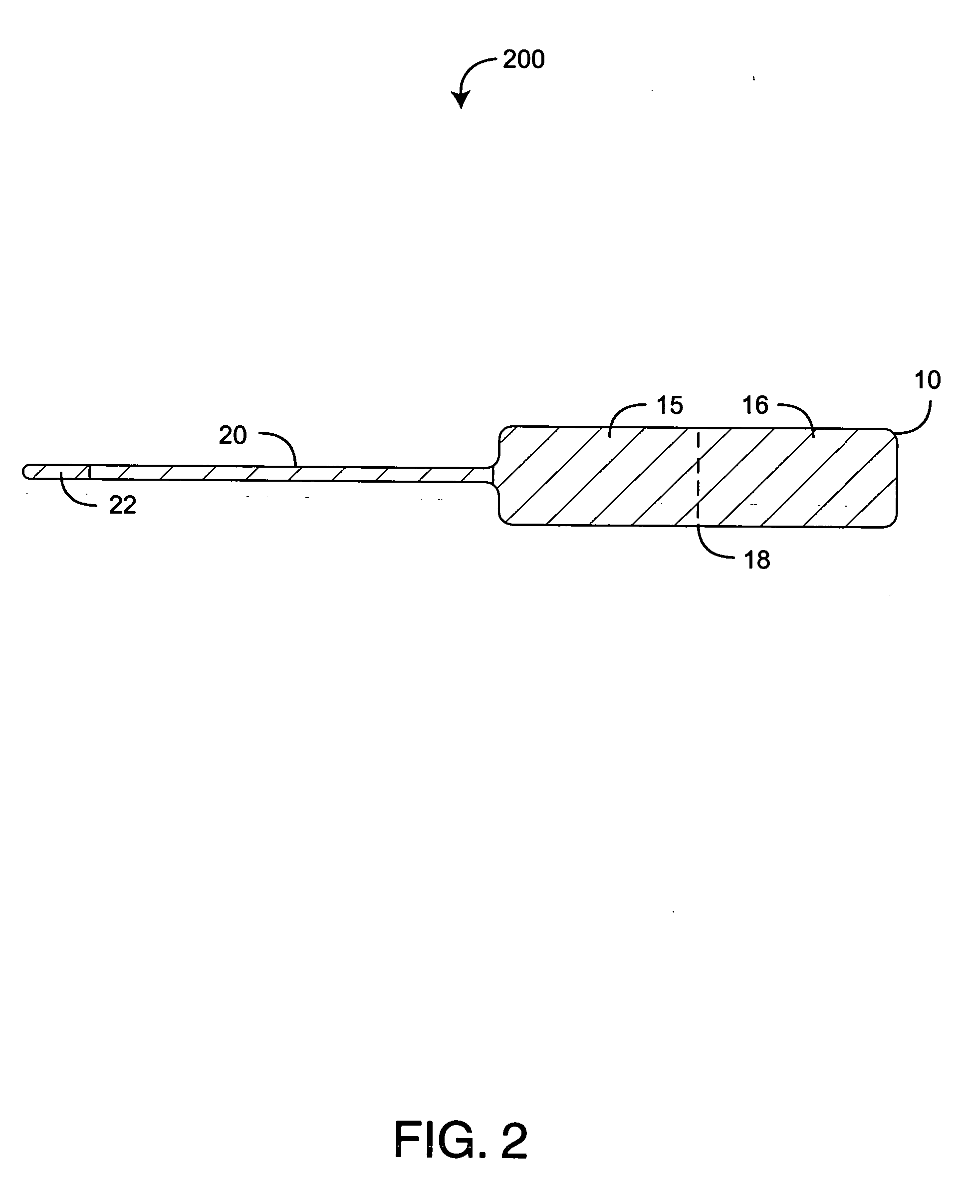
[0022] As shown in FIG. 2, another jewelry tag embodiment 200 has a label 10 and a rat tail shank 20 that are both clear. Printing on the label 10 is visible if held over an opaque background. Otherwise, the entire tag 200 is not readily visible, such as when attached to jewelry in a display case.

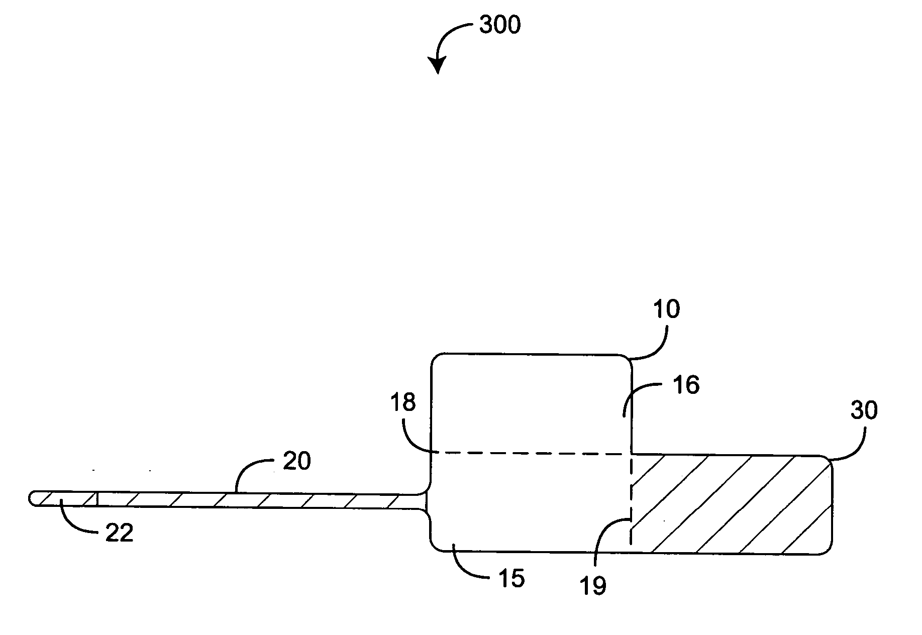
[0023]FIG. 3 illustrates a self-laminating rat tail jewelry tag 300 having a label 10, a rat tail shank 20 and a label fold line 18 that defines sections 15, 16 of the label 10. The jewelry tag 300 further has a flap 30 defined along a flap fold line 19. Advantageously, the flap 30 is adapted to laminate a section of the label 10 and is substantially clear so that printed matter on the laminated label 10 may be read through the flap 30.

[0024] As shown in FIG. 3, the label 10 extends generally perpendicular to the rat tail shank 20, and the flap 30 extends generally inline with the rat tail shank 20. Further, the rat tail shank 20 and the flap 30 extend from opposite ends of a first section...

embodiment 500

[0030] As shown in FIG. 5, a barbell jewelry tag embodiment 500 has a label 50 that is opaque and a bar shank 60 that is clear. In this manner, printing on the label 50 is readily visible, but the bar shank 60 is not readily visible when attached to jewelry in a display case, for example. In a particular embodiment, the bar shank 60 is adhesive free.

[0031] As shown in FIG. 6 a self-laminating barbell jewelry tag 600 embodiment further has a flap 70 advantageously adapted to laminate the label 50. The flap 70 is substantially clear so that printed matter on the laminated label 50 may be read through the flap 70. In one embodiment, individual flaps 75, 76 extend from opposite edges of corresponding label sections 55, 56. In particular, a first flap 75 is defined by a first fold line 45 and extends from one edge of the first section 55 generally perpendicularly to the bar shank 60. A second flap 76 is defined by a second fold line 46 and extends from an opposite edge of the second sect...


PUM


Abstract

A jewelry tag substrate comprises a liner, an adhesive and a clear face stock. The clear face stock has a print side and an adhesive side. The liner is disposed proximate said adhesive side so as to support the face stock. An adhesive is disposed between the liner and the face stock. The liner and the adhesive are adapted so that when portions of the face stock are separated from the liner, the adhesive adheres to the adhesive side. Labels and corresponding shanks are defined by the face stock so that the shanks extend from the labels. A top coat is applied to the print side so that the shanks are substantially clear.

Description

CROSS-REFERENCE TO RELATED APPLICATIONS [0001] This application relates to and claims the benefit of prior U.S. Provisional Application No. 60 / 590,449 entitled Self Laminating Jewelry Tag, filed Jul. 24, 2004 and incorporated by reference herein.BACKGROUND OF THE INVENTION [0002] Jewelry tags are commonly used to label eyeglasses, rings, earrings, bracelets, watches and other jewelry with, for example, price, description, product number and / or bar code information. Jewelry tags come in a variety of shapes and sizes. Tags are typically labeled using direct thermal or thermal transfer printers. Direct thermal printers use a print head composed of a row of closely spaced and individually controlled heating elements and rely on a print medium that changes color when heated above a threshold temperature. Thermal transfer printers use the same type of print head employed in direct thermal machines, but place a ribbon between the print head and the medium. Heat from the print head melts co...

Claims


Application Information

Patent Timeline
IPC IPC(8): B32B33/00
CPCG09F3/14Y10T428/28Y10T428/1486Y10T428/149Y10T428/1495Y10T428/15Y10T428/14Y10T428/24008
Inventor PLUMMER, SEAN A.
Owner PLUMMER SEAN A
Why Eureka
Try Eureka