Wireless repeater with arbitrary programmable selectivity

a repeater and programmable selectivity technology, applied in the field of wireless repeaters, can solve the problems of large repeater size, difficult modification, and high cos

Active Publication Date: 2006-01-26
STRONG FORCE IOT
View PDF31 Cites 81 Cited by
  • Summary
  • Abstract
  • Description
  • Claims
  • Application Information

AI Technical Summary

Problems solved by technology

Many wireless transmitters use circuitry that makes the repeaters large, expensive and difficult to modify.
However, they still rely on repeaters to communicate through large structures, such as shopping malls and the like.

Method used


Image

  • Wireless repeater with arbitrary programmable selectivity
  • Wireless repeater with arbitrary programmable selectivity
  • Wireless repeater with arbitrary programmable selectivity

Examples


Embodiment Construction

)

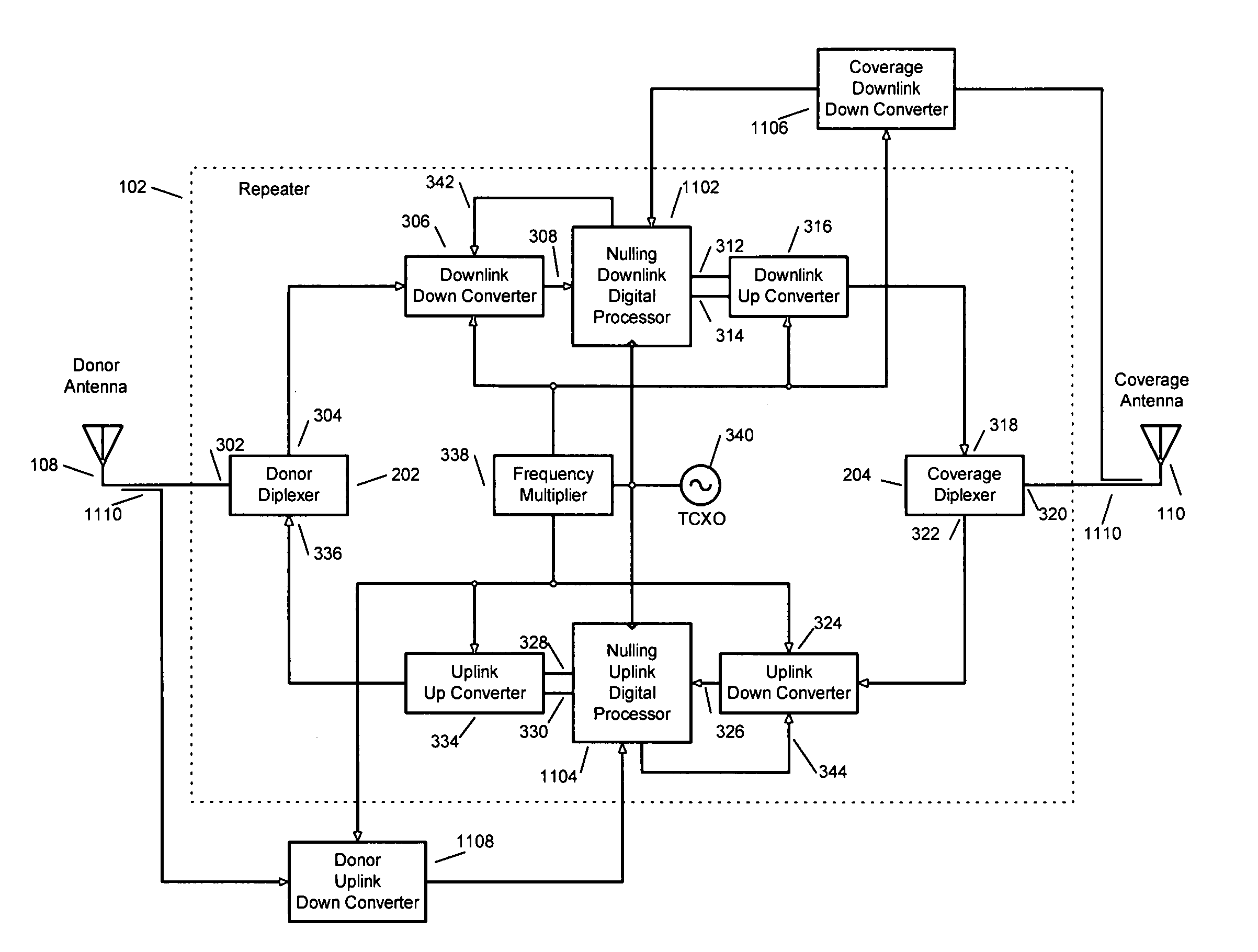
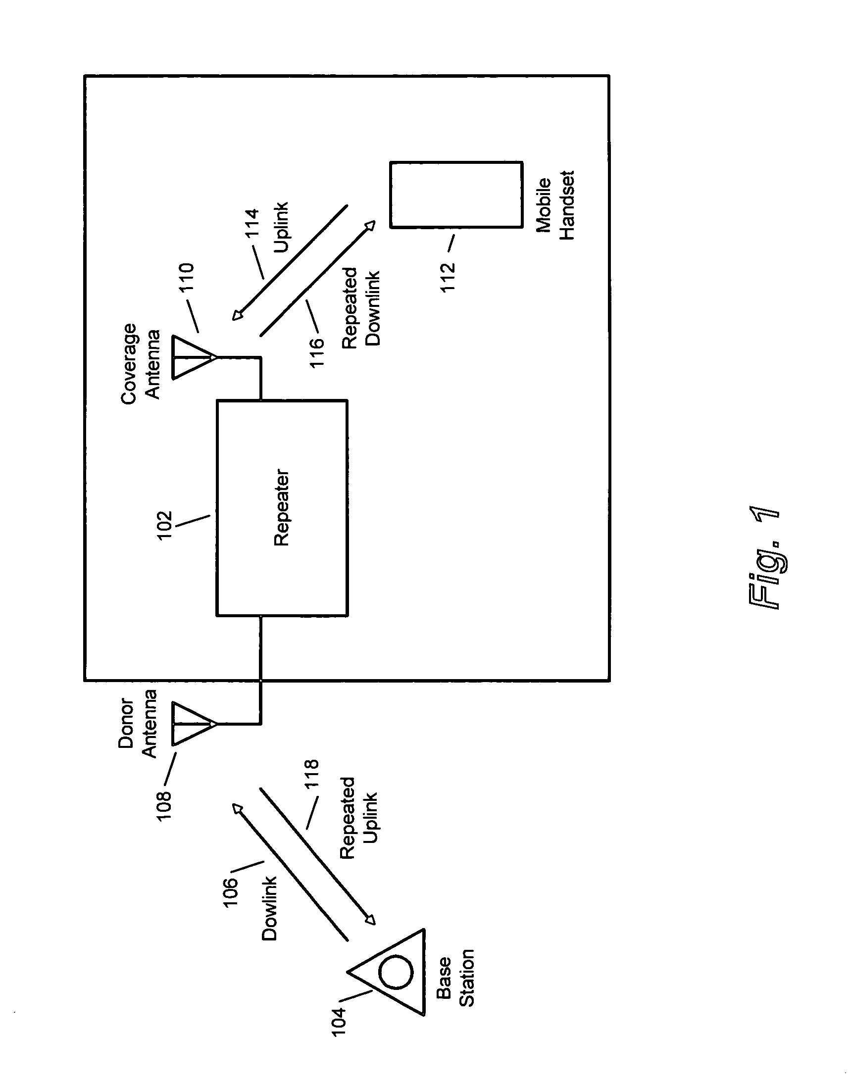
[0019] The present invention relates to techniques that enable implementation of bi-directional repeaters with arbitrary programmable selectivity over the wireless telephony bands. The need for programmable selectivity may be driven by the presence of undesired radio interference and or patterns of frequency allocation by regulatory agencies within a given geographical area.

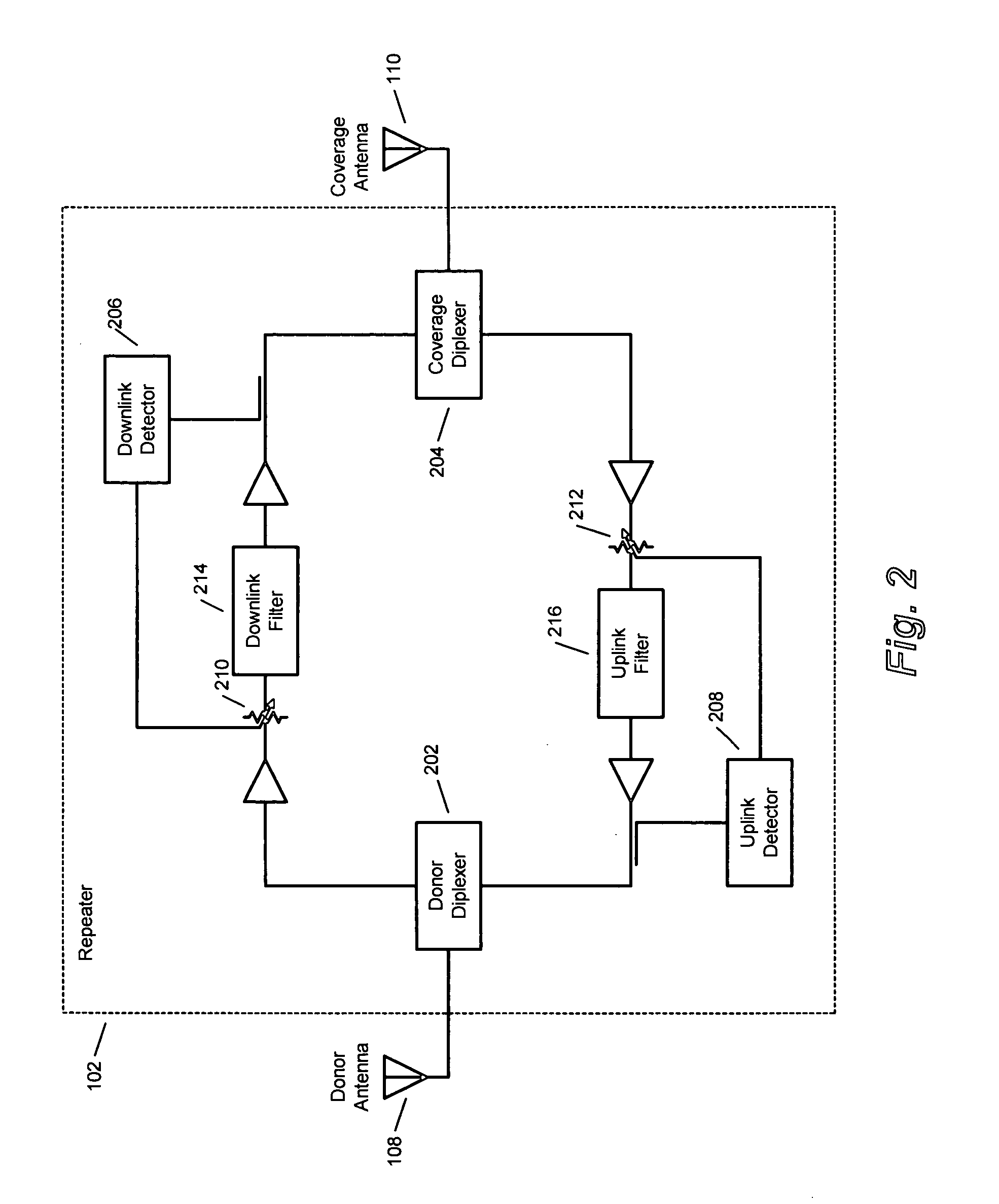
[0020] Typically, a telephony band is partitioned into sub-bands. In order to pass the assigned sub-bands and reject non-assigned bands or radio interference, filtering is required. Conventional analog RF filters at wireless telephony frequencies are costly, large and complex because of Q-factor considerations. By down converting and digitizing the telephony band in question, the filtering problem may be addressed economically. Furthermore, digitizing permits filtering parameters to be changed easily in response to changing conditions and facilitates implementation of additional signal processing techniques (e....


PUM


Abstract

The invention relates to wireless repeater systems and methods. In embodiments, such systems and methods involve receiving a wireless transmission signal; and processing the wireless transmission signal using a digital signal processing facility (DSP); wherein the DSP is adapted to filter at least one sub-band of the wireless transmission signal using a digital bandpass filter.

Description

RELATED APPLICATIONS [0001] This application claims the benefit of, and incorporates by reference herein in its entirety, U.S. Provisional Patent Application No. 60 / 590,318, filed Jul. 22, 2004.BACKGROUND [0002] 1. Field [0003] The present invention relates to wireless communication repeaters; and more particularly, embodiments of the present invention relate to wireless communication repeaters using digital signal processing. [0004] 2. Description of Related Art [0005] Wireless repeaters are generally used to repeat signals and to extend the range of wireless transmitters. Many wireless transmitters use circuitry that makes the repeaters large, expensive and difficult to modify. With the development of cell phone communications came the general desire of people to be continually connected to their cell phone network provider, even in areas where signal strength from the provider is limited. As a result, cell phone carrier providers have been continually increasing the number of tra...

Claims


Application Information

Patent Timeline
Patent Type & Authority Applications(United States)
IPC IPC(8): H04B3/36H04B7/15
CPCH04B7/15542H04W16/26H04B7/15585H04B7/15564H04B1/10H04W84/047
Inventor PERGAL, FRANK
Owner STRONG FORCE IOT
Why Eureka
Try Eureka