Vehicle temperature regulation control unit

a technology for controlling units and vehicles, applied in the direction of process and machine control, instruments, heat measurement, etc., can solve the problem of low and achieve the effect of increasing the degree of freedom in layou

Inactive Publication Date: 2006-02-02
HONDA MOTOR CO LTD
View PDF4 Cites 40 Cited by
  • Summary
  • Abstract
  • Description
  • Claims
  • Application Information

AI Technical Summary

Benefits of technology

[0008] That is, the control unit in the present invention constitutes a single switch with the control member, the switch member, the light-emitting member and the indicator member housed in the single case member. The control member and the indicator member can be advantageously mounted in a space approximately equal to that for a general switch, resulting in an increased degree of free

Problems solved by technology

The control unit 201 thus becomes large, res

Method used


Image

  • Vehicle temperature regulation control unit
  • Vehicle temperature regulation control unit
  • Vehicle temperature regulation control unit

Examples


Embodiment Construction

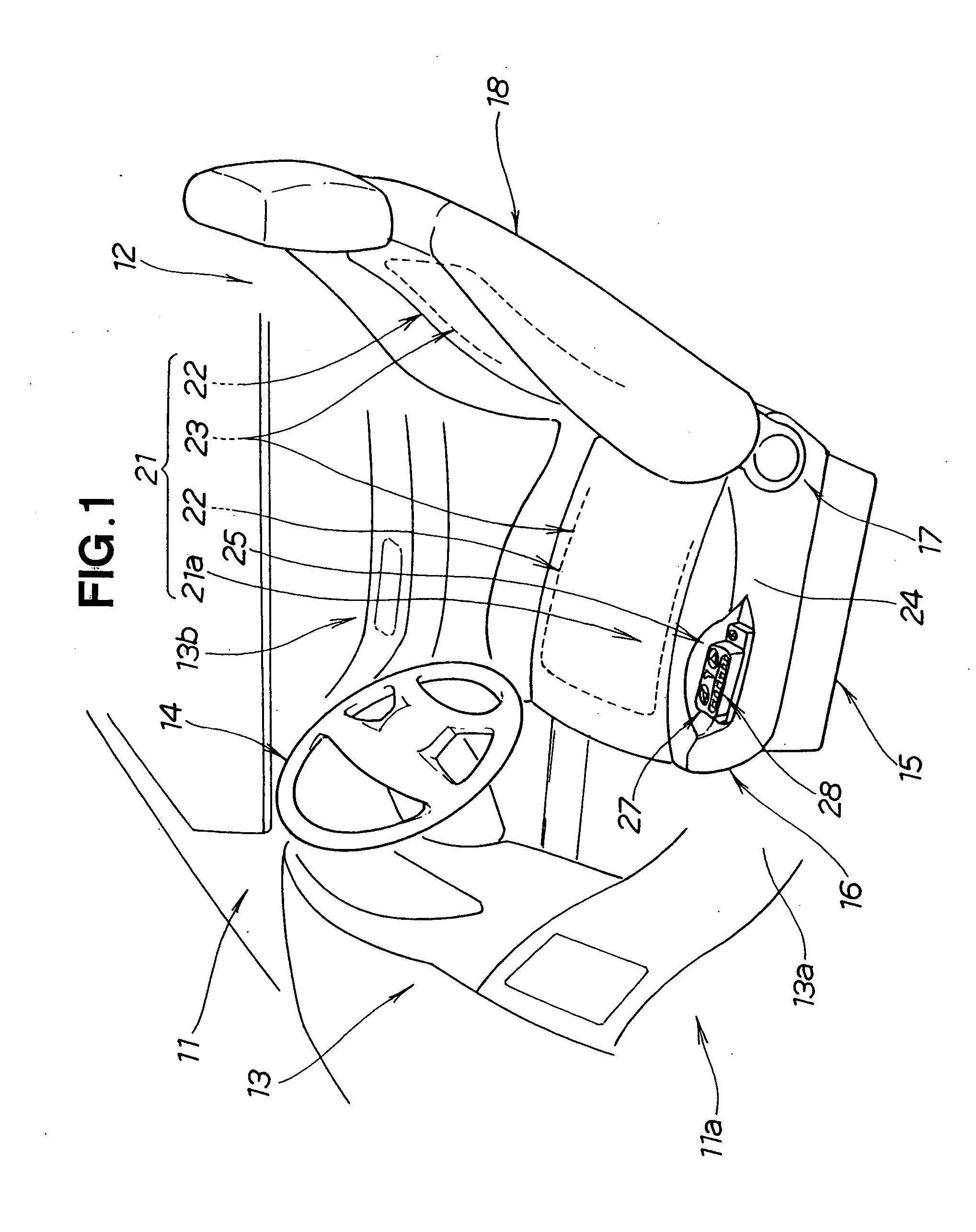
[0023] In front of a driver seat (vehicle seat) 12 shown in FIG. 1, an instrument panel 13 and a steering wheel 14 are disposed. Reference sign Ha denotes a passenger compartment.

[0024] The driver seat 12 includes a seat cushion 16 placed on a sliding mechanism 15, a seatback 18 attached to the seat cushion 16 via a reclining mechanism 17, and a seat temperature regulating system 21.

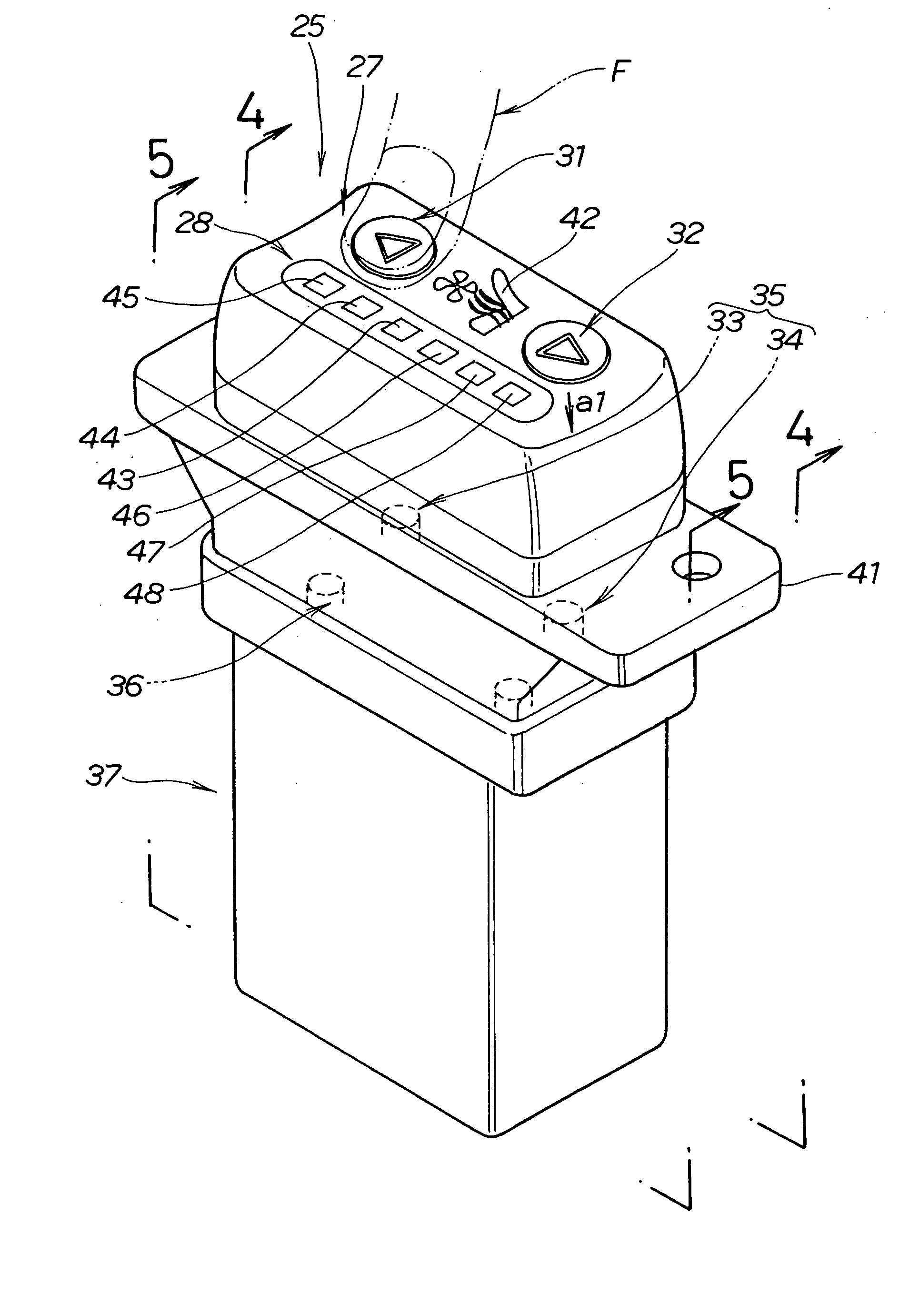
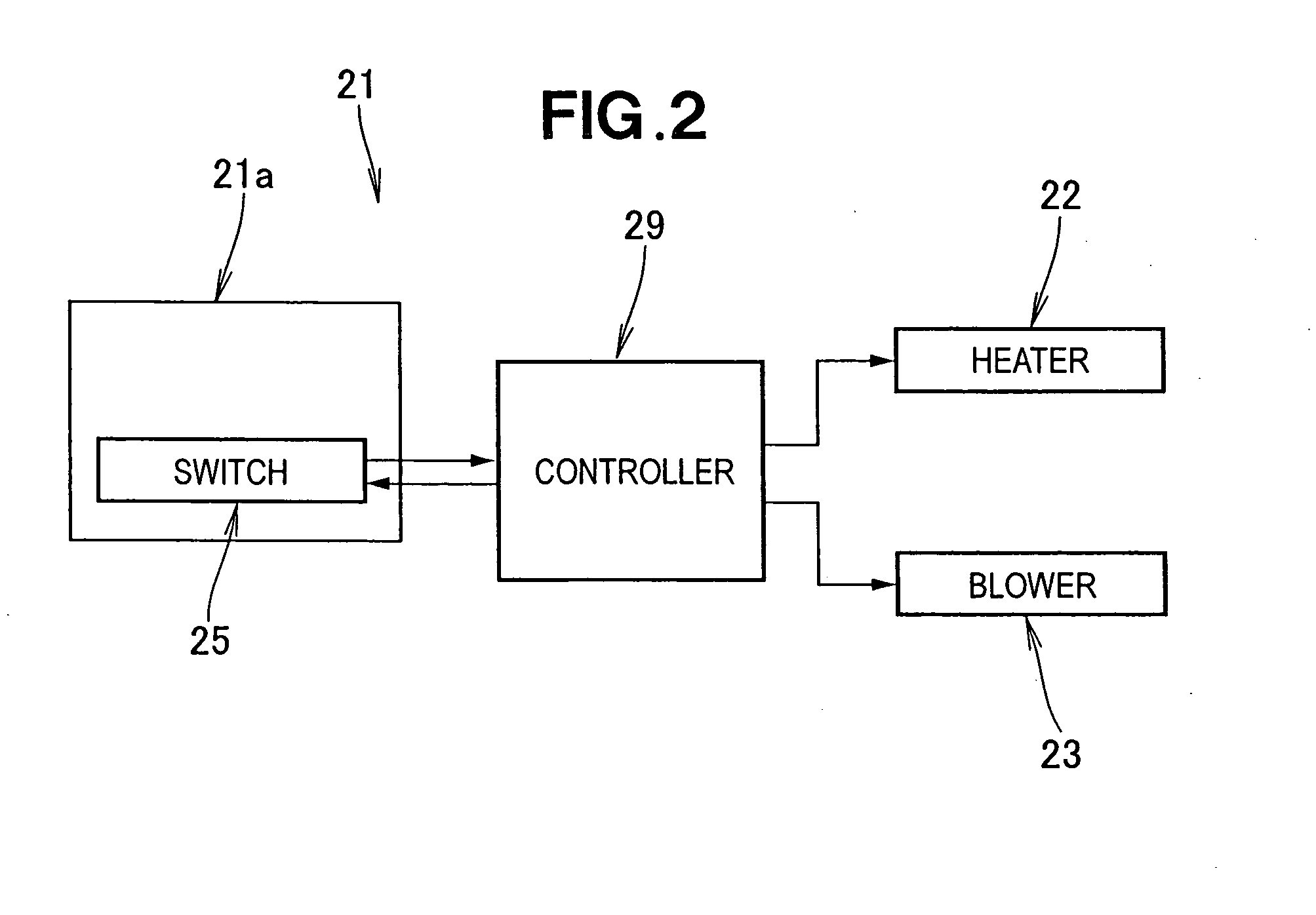
[0025] The seat temperature regulating system 21 regulates the temperature of the driver seat 12 to a desired temperature, and includes heaters 22, 22 and blowers 23, 23 provided in the seat cushion 16 and the seatback 18, and a temperature regulation control unit 21a for setting the temperature, disposed at a left side portion 24 of the seat cushion 16. The temperature regulation control unit 21a has a switch 25.

[0026] The switch 25 includes a control member 27 for setting the amount of warm air or the amount of cool air, and an indicator member (indicator) 28 for indicating the setting via the contr...


PUM


Abstract

A control unit including a switch for regulating the temperature of a passenger compartment and/or the temperature of a vehicle seat. The switch is of a unit type with a control member, a switch member, a light-emitting member, and an indicator member housed in a single case, and can be disposed anywhere near a driver.

Description

FIELD OF THE INVENTION [0001] The present invention relates to temperature regulation control units having a switch for regulating the temperature of a passenger compartment or the temperature of a vehicle seat. BACKGROUND OF THE INVENTION [0002] An air-conditioning apparatus provided with a switch for regulating the temperature of a passenger compartment or the temperature of a vehicle seat is proposed in Japanese Patent Laid-Open Publication No. HEI-9-115376, for example. A control unit of this air-conditioning apparatus will be described with reference to FIGS. 11A and 11B hereof. [0003] A control unit 201 of a vehicle air-conditioning apparatus shown in FIG. 11A includes a printed circuit board 205 on which a number of mounted switches 202, light-emitting diodes 203 and an LCD panel are mounted, a flexible printed circuit board 207 on which chip LEDs 206 are mounted at locations opposite to the mounted switches 202, and switch knobs 209 having control panels 208. The control pan...

Claims


Application Information

Patent Timeline
IPC IPC(8): G05D23/00G01K13/00B60H1/32
CPCB60H1/00985
Inventor MIZUKOSHI, TAKEO
Owner HONDA MOTOR CO LTD
Why Eureka
Try Eureka