
Numerical control device

a control device and number technology, applied in the direction of program control, electric programme control, instruments, etc., can solve the problems of tool breakage and the like, motor rotates at a low speed, and the main spindle is abnormally rotated,

Inactive Publication Date: 2006-02-02
FANUC LTD
View PDF7 Cites 2 Cited by
  • Summary
  • Abstract
  • Description
  • Claims
  • Application Information

AI Technical Summary

Benefits of technology

[0019] As described above, the numerical control device according to the present invention makes it possible to detect abnormality of analog voltage of a speed instruction in an analog spindle control, whereby abnormal rotation and malfunction of the motor can be prevented.

Problems solved by technology

However, an analog voltage generated in practice, necessarily includes an error with respect to the speed instructed by the numerical control device 10, and an error is also generated on the side of the analog amplifier 20 receiving the instruction.
This becomes a problem in particular when a speed “0” is instructed.
That is, there arises a problem that in spite of the fact that a speed 0 is instructed, the motor rotates at a low speed (at a speed not equal to 0) due to the error of the analog voltage.
The conventional numerical control device is not provided with a system for checking whether the analog voltage outputted as the speed instruction is normal or not, so that a machine and device such as a machine tool, which are controlled by the numerical control device, may perform an abnormal operation.
This is not preferred and dangerous.
For example, in the case where the motor under the analog spindle control is a main spindle motor of a machine tool, such failure causes the main spindle to abnormally rotate.
As a result, when normal working can not be performed, a tool breakage and the like may occur.

Method used


Image

  • Numerical control device
  • Numerical control device
  • Numerical control device

Examples


Embodiment Construction

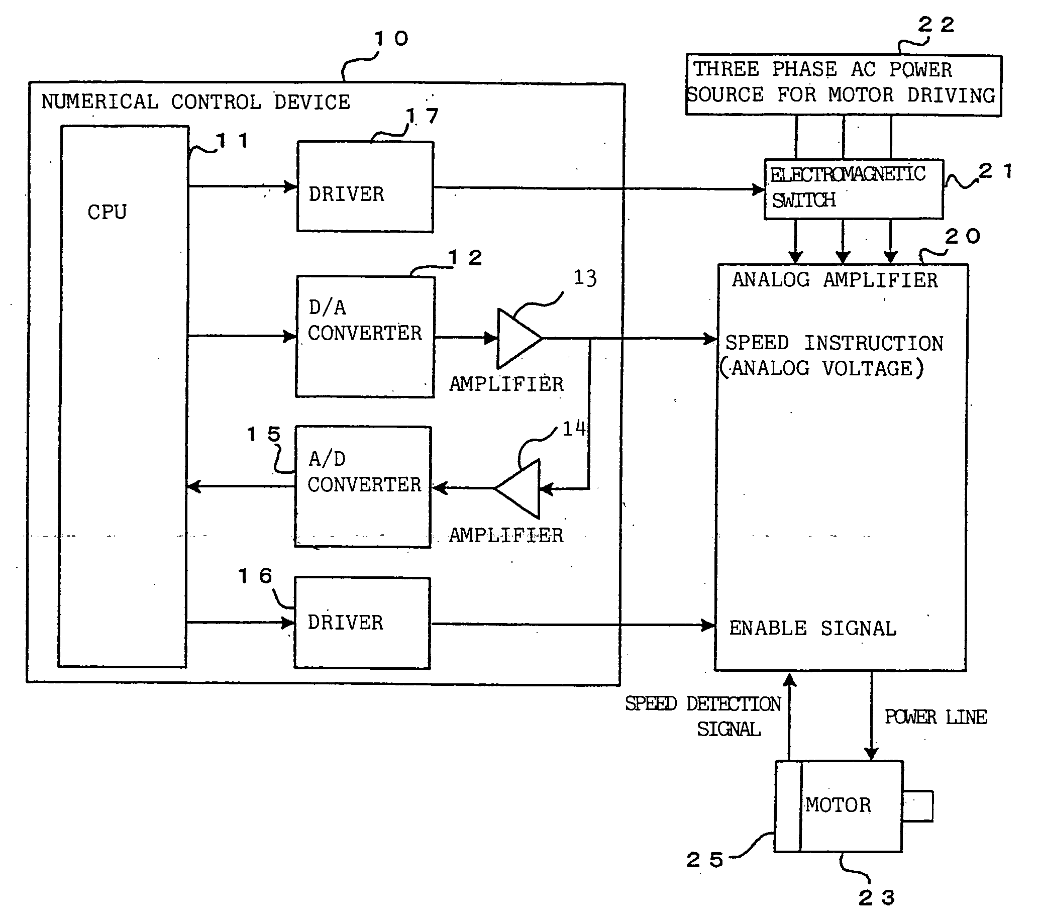
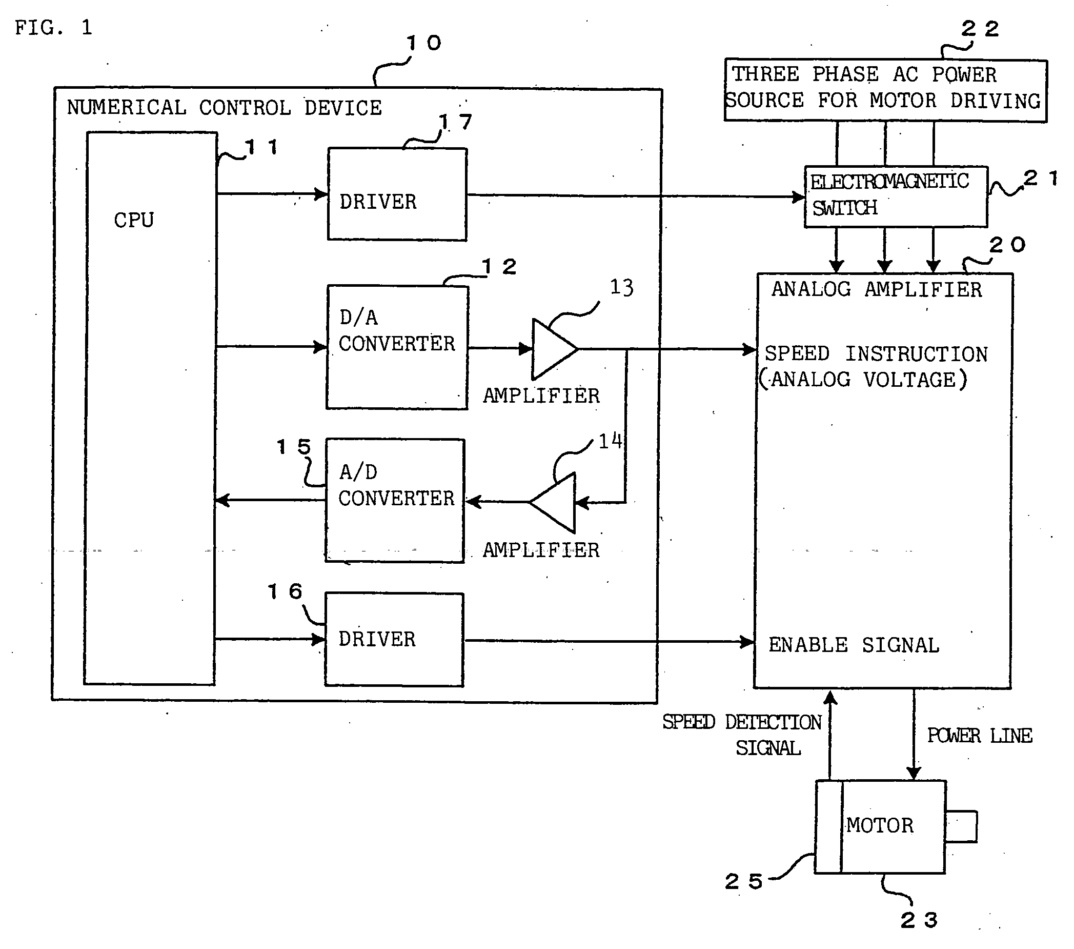
[0027]FIG. 1 shows a main part of a numerical control device of an embodiment according to the present embodiment, and a system configuration of analog spindle motor drive control performed by the numerical control device.

[0028] The system of analog spindle motor drive control performed by the numerical control device shown in FIG. 1 is different from the system of analog spindle motor drive control performed by the conventional numerical control device shown in FIG. 6, in that the system shown in FIG. 1 comprises an amplifier 14 which receives an analog voltage of a speed instruction outputted to the analog amplifier 20, and converts the analog voltage into a predetermined voltage, and an A / D converter 15 which converts the analog voltage from the amplifier 14 into a digital value, and outputs the digital value to the CPU 11, and in that enable signal processing and emergency stop signal processing, as will be described below, are performed. In FIG. 1, components corresponding to ...


PUM


Abstract

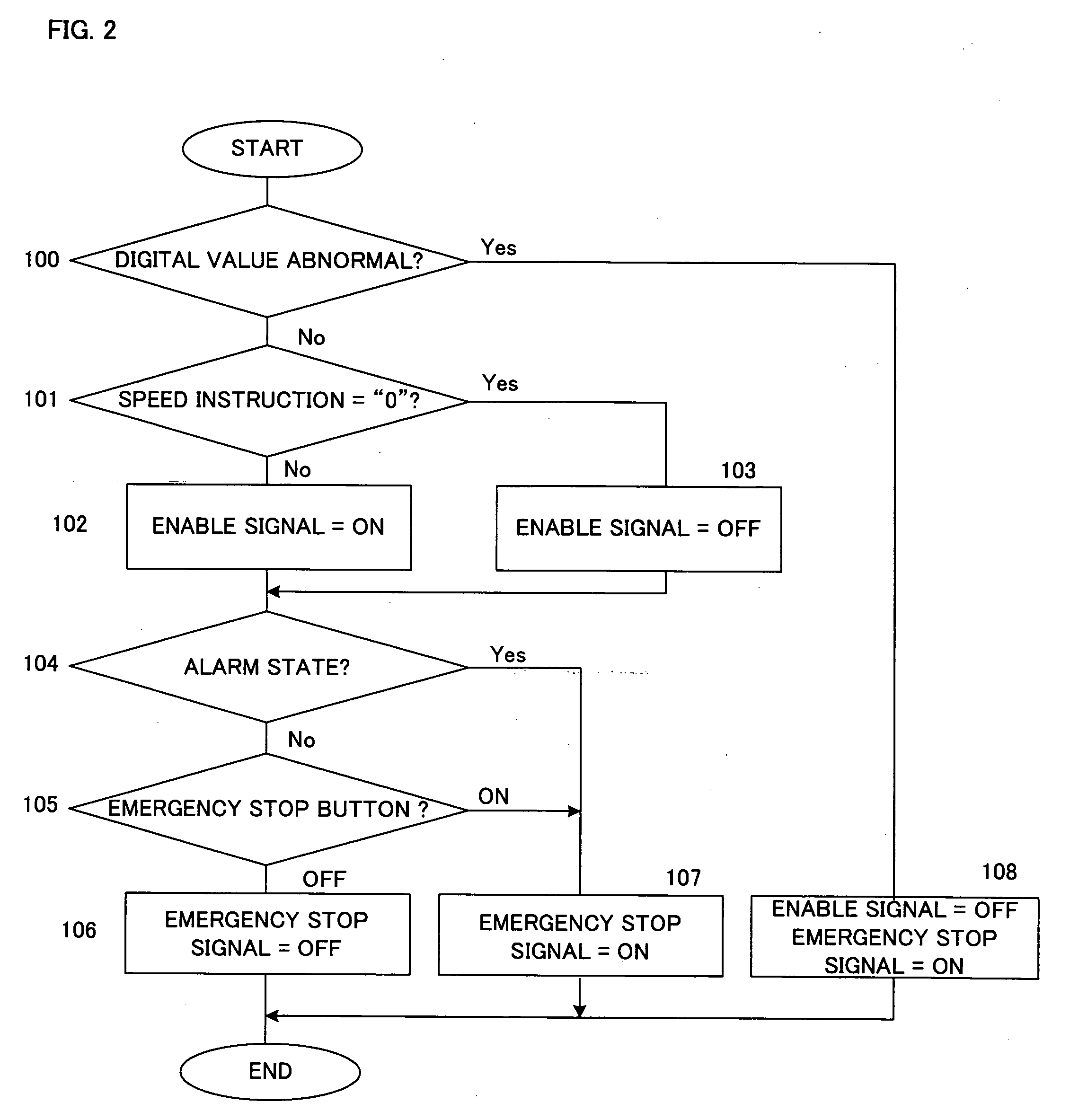
An analog amplifier performs control of a motor at the speed in proportion to a speed instruction (analog voltage) outputted from a numerical control device. The speed instruction (analog value) is converted into a digital value by an A / D converter and is then sent to a CPU. When the CPU judges that the received digital value corresponding to the speed instruction deviates from a predetermined range, the CPU stops sending out an enable signal, and sends out an emergency stop signal. As a result, the CPU stops electric power supply to the analog amplifier, and also invalidates the speed instruction sent to the analog amplifier 20, thereby performing control to make the speed of the motor become “0”.

Description

BACKGROUND OF THE INVENTION [0001] 1. Field of the Invention [0002] The present invention relates to a numerical control device which controls a machine tool and the like. [0003] 2. Description of the Related Art [0004]FIG. 5 shows a system configuration of a motor subjected to an analog spindle control performed by a numerical control device. An analog voltage (a speed instruction) for analog spindle control is applied to an amplifier of a motor (for example, a main spindle motor) from a numerical control device 10 and the motor is rotated at the speed in proportion to the applied analog voltage. [0005] Specifically, the numerical control device 10 normally outputs an analog voltage from −10 V to +10V to an analog amplifier 20 as speed instruction for analog spindle control. The analog amplifier 20 amplifies electric power supplied via an electromagnetic switch 21 from a three phase AC power source 22 for motor driving in proportion to the analog voltage of the speed instruction, a...

Claims


Application Information

Patent Timeline
Patent Type & Authority Applications(United States)
IPC IPC(8): G05B19/18
CPCH02P23/03
Inventor AOYAMA, KAZUNARIKOMAKI, KUNITAKAAIZAWA, YASUHARU
Owner FANUC LTD
Learn More