Method and apparatus for fail-safe resynchronization with minimum latency

a synchronization and minimum latency technology, applied in the direction of synchronization signal speed/phase control, instruments, generating/distributing signals, etc., can solve the problems of freezing the latency period of circuit operation, freezing the clock selection, etc., and achieve the effect of stable operating configuration

Inactive Publication Date: 2006-02-02
RAMBUS INC
View PDF26 Cites 59 Cited by
  • Summary
  • Abstract
  • Description
  • Claims
  • Application Information

AI Technical Summary

Benefits of technology

[0008] The present invention provides a synchronization circuit having two latching circuits which latch data from a receive clock domain on both the rising and falling edges of a transmit clock. The selection of which latch data to use is based on a phase measurement of the phase difference between the receive and transmit clocks, which provides a select signal to a multiplexer connected to the two latching circuits. The phase difference is chosen to provide data which is as close as possible to the middle of an overlap region of valid data for the two latches. Once this value has been chosen, it is frozen in a latch after initialization. Since the data could have one, two or more clock cycle latencies from its origin, freezing the clock selection also freezes the latency period for operation of the circuit. Thus, although the synchronization circuit only knows the relative phase difference, not the latency, it can establish a stable operating configuration.
[0010] In a preferred embodiment, the receive clock domain data is provided through a flip-flop clocked by a receive clock. The two latching circuits are preferably flip-flops utilizing a precharged sense amp in order to minimize shifting of the clock due to set-up, hold and clock-to-data-out variations.

Problems solved by technology

Since the data could have one, two or more clock cycle latencies from its origin, freezing the clock selection also freezes the latency period for operation of the circuit.

Method used


Image

  • Method and apparatus for fail-safe resynchronization with minimum latency
  • Method and apparatus for fail-safe resynchronization with minimum latency
  • Method and apparatus for fail-safe resynchronization with minimum latency

Examples


Embodiment Construction

Overview of Invention

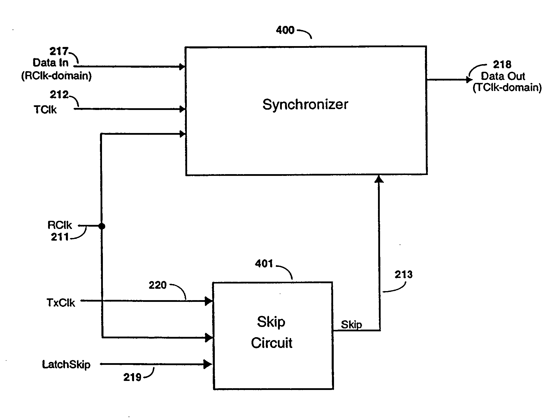
[0041] This invention makes it possible to take input data of arbitrary phase and re-time it into a second mesochronous clock domain with minimal latency. A block diagram of the preferred embodiment is shown in FIG. 6. It achieves this re-timing via the Synchronizer 400 and the Skip Circuit 401. Each of these distinct circuits and their functions will be described separately, with their operation together described last.

Definitions

[0042] There are several terms which aid in the following discussion of the invention.

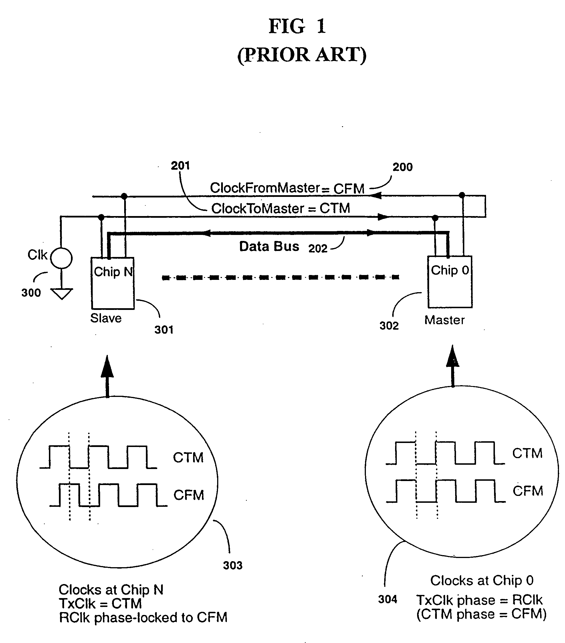
[0043] Rclk: Clock phase-locked to Bus-receive clock (204 in FIG. 5). Duty-cycle corrected.

[0044] TxClk: Transmit clock as seen on Bus. TxClk lags TClk by 90° (203 in FIG. 5). Not duty-cycle corrected.

[0045] Tclk: Clock signal in quadrature with TxClk to facilitate centering of output data around transmit clock. Duty-cycle corrected.

[0046] tTR: Time delay from TxClk to RClk divided by the clock cycle-time. This number can also be expressed as a...


PUM


Abstract

A method and circuit for achieving minimum latency data transfer between two mesochronous (same frequency, different phase) clock domains is disclosed. This circuit supports arbitrary phase relationships between two clock domains and is tolerant of temperature and voltage shifts after initialization while maintaining the same output data latency. In one embodiment, this circuit is used on a bus-system to re-time data from receive-domain, clocks to transmit-domain clocks. In such a system the phase relationships between these two clocks is set by the device bus location and thus is not precisely known. By supporting arbitrary phase resynchronization, this disclosure allows for theoretically infinite bus-length and thus no limitation on device count, as well as arbitrary placement of devices along the bus. This ultimately allows support of multiple latency-domains for very long buses.

Description

RELATED APPLICATIONS [0001] This application is a continuation of patent application Ser. No. 10 / 282,531, filed Oct. 28, 2002, now U.S. Pat. No. 6,949,958, which was a continuation of patent application Ser. No. 09 / 169,372, filed Oct. 9, 1998, now U.S. Pat. No. 6,473,439, which claimed priority to the provisional patent application entitled “Method and Apparatus for Fail-Safe Resynchronization with Minimum Latency”, Ser. No. 60 / 061,505, filed Oct. 10, 1997.BACKGROUND OF THE INVENTION [0002] The present invention relates to circuits for synchronizing data transfer between clock domains of the same frequency but different phase, in particular for synchronous memory systems. [0003] Mesochronous systems consist of two or more different clocks running at the same frequency with an arbitrary phase relationship. In such systems synchronization failures-can occur when passing data from one clock domain into another. While this problem is similar to that of asynchronous systems, it is easier...

Claims


Application Information

Patent Timeline
Patent Type & Authority Applications(United States)
IPC IPC(8): H03L7/00G06F1/10G06F13/42H04L7/00H04L7/02H04L7/033H04L7/04
CPCG06F1/12G06F13/423H03L7/085H04L7/0337H04L7/0054H04L7/02H04L7/0012H04L7/0045
Inventor ZERBE, JARED LEVANCHING, MICHAEL TAK-KEIABHYANKAR, ABHIJIT M.BARTH, RICHARD M.CHAN, ANDY PENG-PUIDAVIS, PAUL G.STONECYPHER, WILLIAM F.
Owner RAMBUS INC
Why Eureka
Try Eureka