Apparatus and methods for scanning conoscopic holography measurements

a conoscopic holography and holography technology, applied in the field of measuring systems, can solve the problems of inacceptable measurement errors, adding to the overall cost and complexity of the manufacturing and assembly process,

Inactive Publication Date: 2006-02-02
THE BOEING CO
View PDF13 Cites 12 Cited by
  • Summary
  • Abstract
  • Description
  • Claims
  • Application Information

AI Technical Summary

Benefits of technology

[0005] The present invention is directed to measurement systems, and more specifically, to scanning conoscopic holography measurement systems. Embodiments of apparatus and methods in accordance with the present invention may advantageously reduce the number of measurement gauges that would otherwise be needed in the manufacturing and assembly of large, complex structures, and may reduce or eliminate the errors that may occur due to assumptions inherent in the measurement procedure.
[0006] In one embodiment, a system for performing a measurement of a physical characteristic of a workpiece includes a conoscopic holography sensor, a beam directing assembly, and a control assembly. The conoscopic holography sensor is adapted to emit a laser beam, and the beam directing assembly is adapted to receive the laser beam and to adjustably direct the laser beam toward the workpiece. The beam directing assembly is further adapted to receive reflected light back from the workpiece and to direct the reflected light toward the conoscopic holography sensor. The control assembly controls the timing of the emission of the laser beam and its direction, each of which is adjustable independently to effect the desired scanning measurement.
[0008] In another alternate embodiment, the system further includes a calibration assembly operatively coupled to at least one of the conoscopic holography sensor and the beam directing assembly. The calibration assembly includes a positioning assembly, a camera, and a processor. The positioning assembly has a carriage operatively coupled to at least one of the conoscopic holography sensor and the beam directing assembly and is adapted to adjustably position the carriage. The camera is positioned proximate to the carriage and is adapted to receive the laser beam from the beam directing assembly and to transmit a corresponding image signal to the processor which, in turn, transmits a corresponding calibration signal to the control assembly. In one particular embodiment, the positioning assembly includes a three axis stage that provides position control along first, second, and third directions. The calibration control signal allows proper calibration of the conoscopic holography sensor prior to making actual measurements.

Problems solved by technology

For example, in some circumstances, the assumptions included in the operation of a measurement gauge may cause measurement errors that are unacceptable.
Furthermore, because the prior art measurement gauges are specialized to a particular purpose, a large number of such gauges may be needed, adding to the overall cost and complexity of the manufacturing and assembly process.

Method used


Image

  • Apparatus and methods for scanning conoscopic holography measurements
  • Apparatus and methods for scanning conoscopic holography measurements
  • Apparatus and methods for scanning conoscopic holography measurements

Examples


Embodiment Construction

[0019] The present invention relates to measuring or otherwise analyzing characteristics of a workpiece using conoscopic holography. While details of certain embodiments are described and shown, other embodiments may be used, including some embodiments that omit some details from the embodiments that we choose to describe as representative of the present invention.

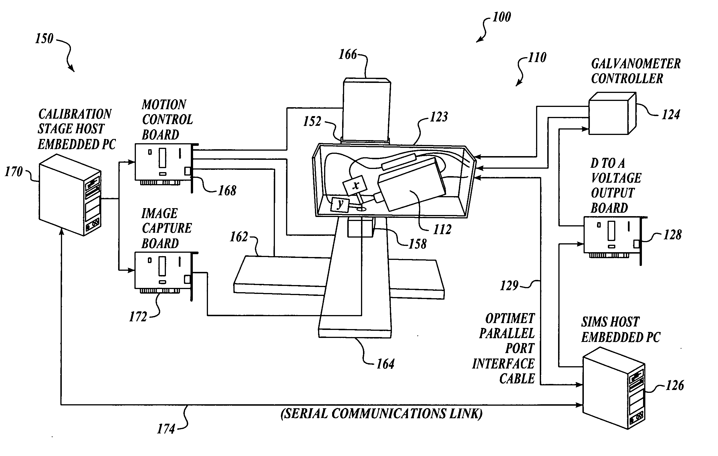
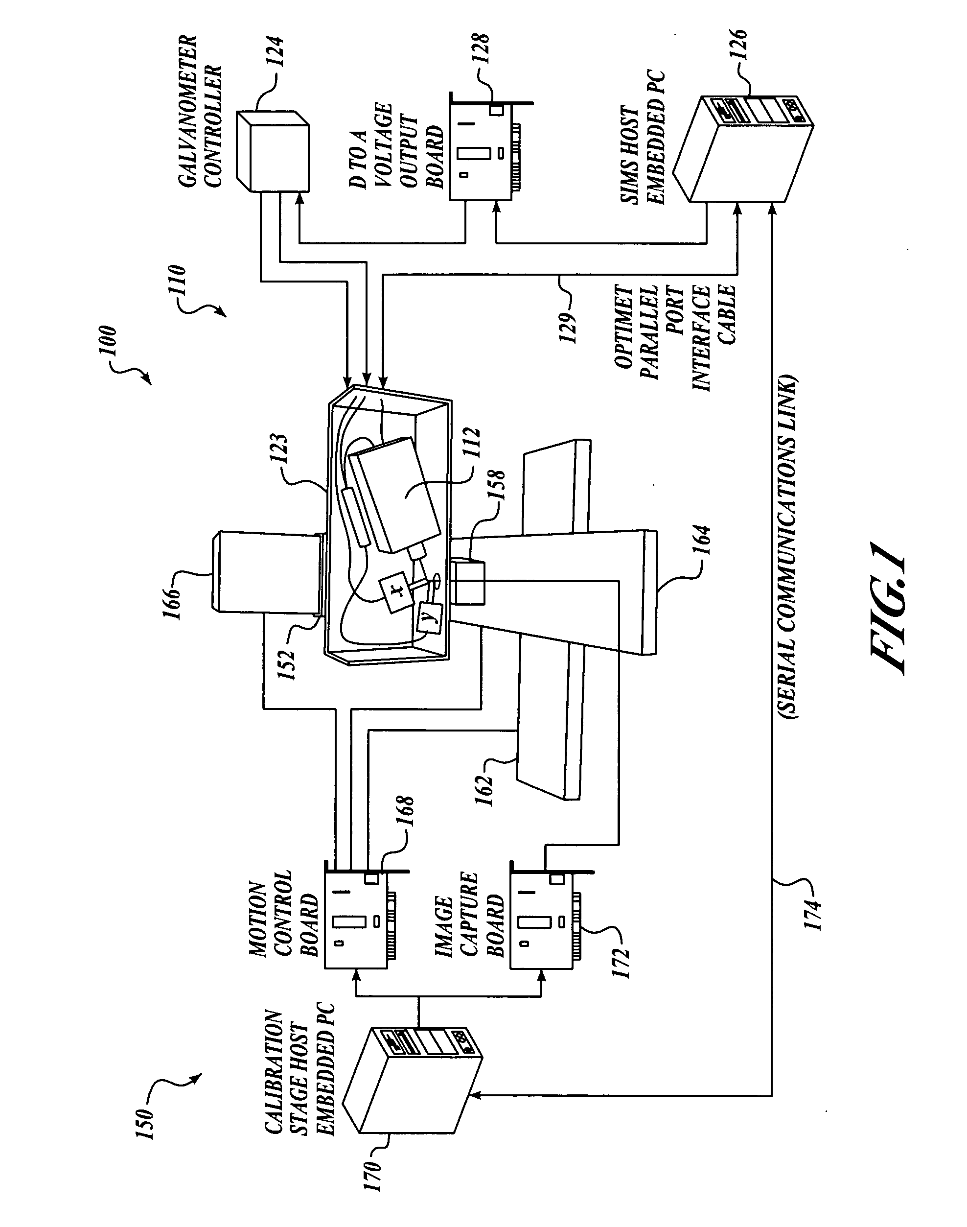
[0020]FIG. 1 is a schematic view of a measurement system 100 in accordance with one embodiment that includes a data acquisition assembly 110 and a calibration assembly 150. The data acquisition assembly 110 performs measurements on a workpiece, while the calibration assembly 150 enables the proper calibration of the data acquisition assembly 110. Embodiments of systems and methods in accordance with the present invention may be used to perform measurements of a variety of physical characteristics of the workpiece, including, for example, angles, distances, roughness, scratches, hole diameters and other hole characteristic...


PUM


Abstract

Apparatus and methods for scanning conoscopic holography measurements are disclosed. In one embodiment, a system includes a conoscopic holography sensor, a beam directing assembly, and a control assembly. The beam directing assembly is adapted to adjustably direct a laser beam from the sensor toward the workpiece, and to direct a reflected light from the workpiece into the sensor. The control assembly controllably adjusts a direction of the laser beam into a desired position on the workpiece. In one particular embodiment, the beam directing assembly includes first and second mirrors coupled to first and second galvanometers for controllably directing the laser beam along first and second axes, respectively. Alternately, the system includes a calibration assembly having a three axis stage for performing calibrations of the laser beam location.

Description

FIELD OF THE INVENTION [0001] This invention relates to measurement systems, and more specifically, to scanning conoscopic holography measurement systems. BACKGROUND OF THE INVENTION [0002] Conventional manufacturing and assembly of large, complex structures, such as large commercial aircraft and the like, may involve hundreds of single purpose measurement gauges. Each such measurement gauge typically has a specific function, and when a new function is required, a new measurement gauge is designed and fabricated. [0003] In addition, many conventional measurement gauges include an assumption about some aspect of the inspected feature's geometry. For example, a countersink diameter gauge may be based on an assumption that the hole is round, and that there are no chamfers at the edge where the conical stylus of the gauge makes contact. Such gauges typically provide accurate measurements provided that these assumptions are satisfied. [0004] Although desirable results have been achieved ...

Claims


Application Information

Patent Timeline
Patent Type & Authority Applications(United States)
IPC IPC(8): G01B9/021
CPCG01B9/021G03H1/06G03H1/0493
Inventor BENNISON, STEPHEN J.
Owner THE BOEING CO
Why Eureka
Try Eureka