
Color image forming apparatus and process cartridge

a technology of color image and process cartridge, which is applied in the direction of digitally marking record carriers, visual presentation using printers, instruments, etc., can solve the problems of color image forming apparatuses that require a higher resolution than ever before, color shift by one line period, and image degradation

Inactive Publication Date: 2006-02-02
RICOH KK
View PDF16 Cites 37 Cited by
  • Summary
  • Abstract
  • Description
  • Claims
  • Application Information

AI Technical Summary

Benefits of technology

The present invention provides a color image forming apparatus and process cartridge that can solve the problems in conventional technology. The apparatus includes a plurality of light sources, a rotating polygon mirror, and a plurality of light receiving elements to create synchronization detection signals for the start position of an optical writing. Each write controller makes a transfer request for image data based on the synchronization detection signals and a reference time. The technical effect of this invention is to improve the accuracy and efficiency of color image formation.

Problems solved by technology

However, recently available color image forming apparatuses require higher resolution than ever before.
Therefore, misregistrations between the images lead to color shifts, causing a degradation of the image.
Therefore, displacement for a line period occurs between image formations for the colors according to the operation start signal and the timing of the synchronization detection signal for each color, which results in occurrence of color shift for each color on the registration position in the sub-scanning direction, which causes occurrence of the color shift by one line period at maximum.
In such a case, if the timing of an input of the operation start signal is synchronized to the synchronization detection signal, it is disadvantage that a determining unit causes timings of starting image formation of write controllers to be different so that each of the write controllers differently controls optical writing to form an electrostatic latent image.

Method used


Image

  • Color image forming apparatus and process cartridge
  • Color image forming apparatus and process cartridge
  • Color image forming apparatus and process cartridge

Examples


Embodiment Construction

[0028] Exemplary embodiments of a color image forming apparatus and a process cartridge according to the present invention are explained in detail below with reference to the accompanying drawings.

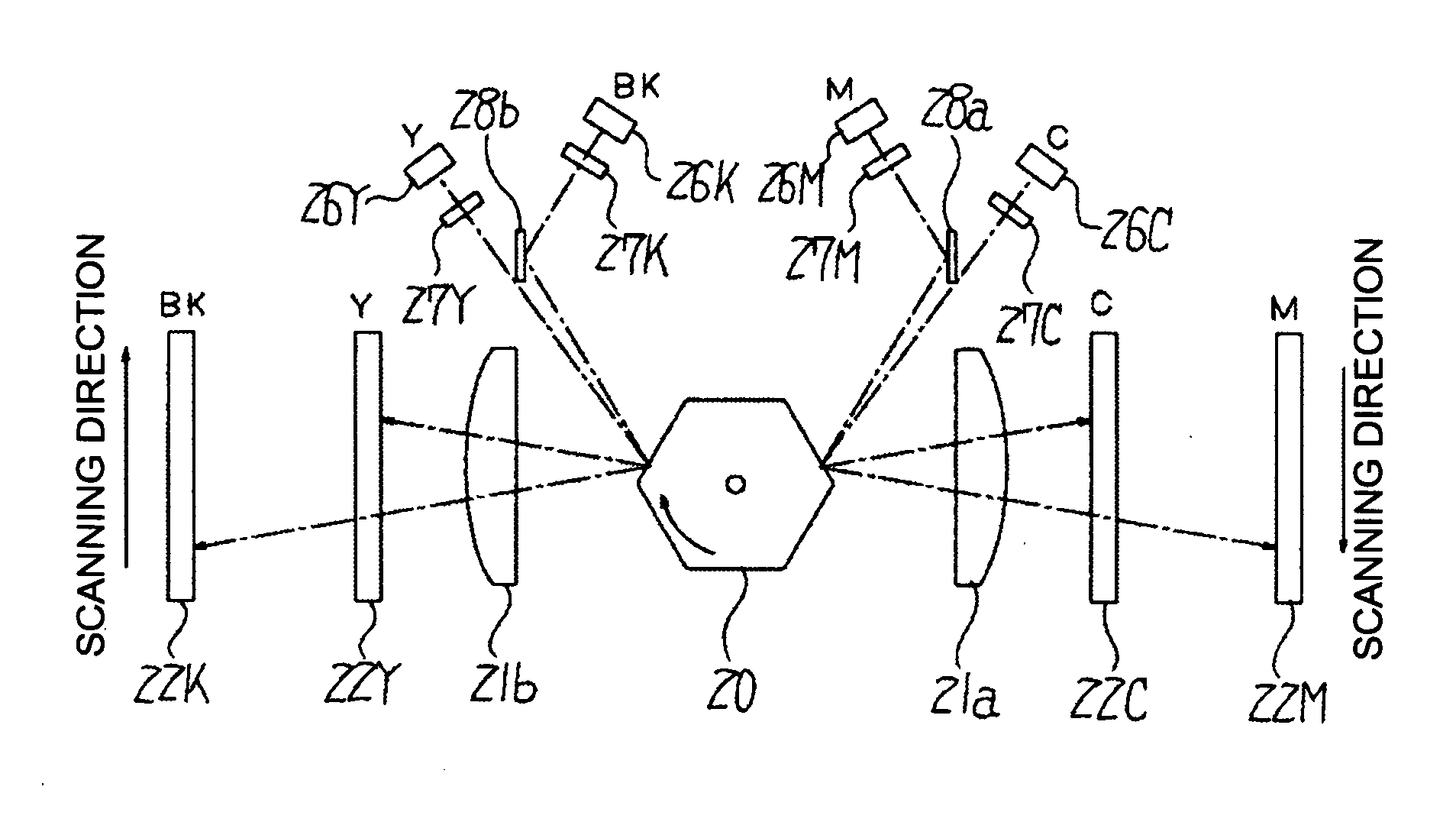
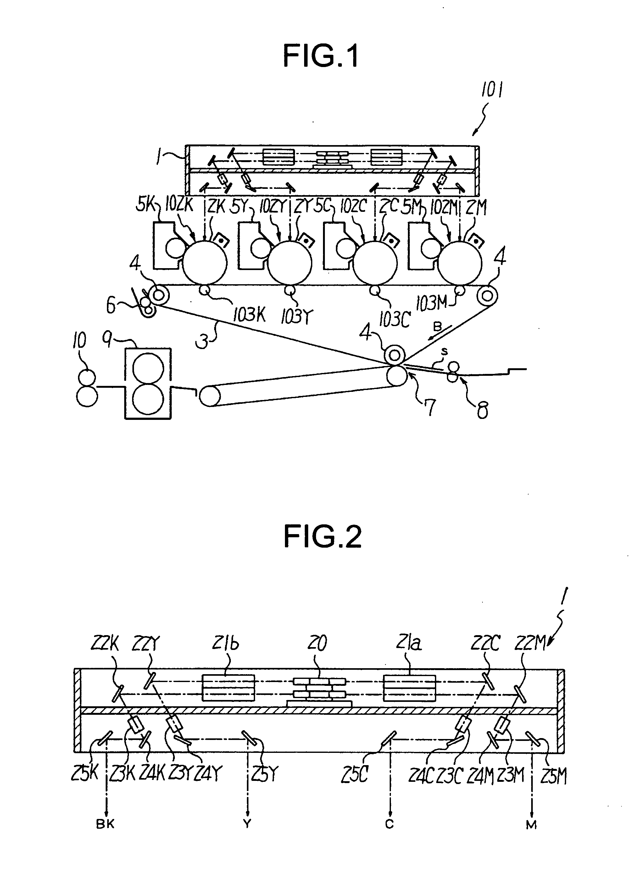
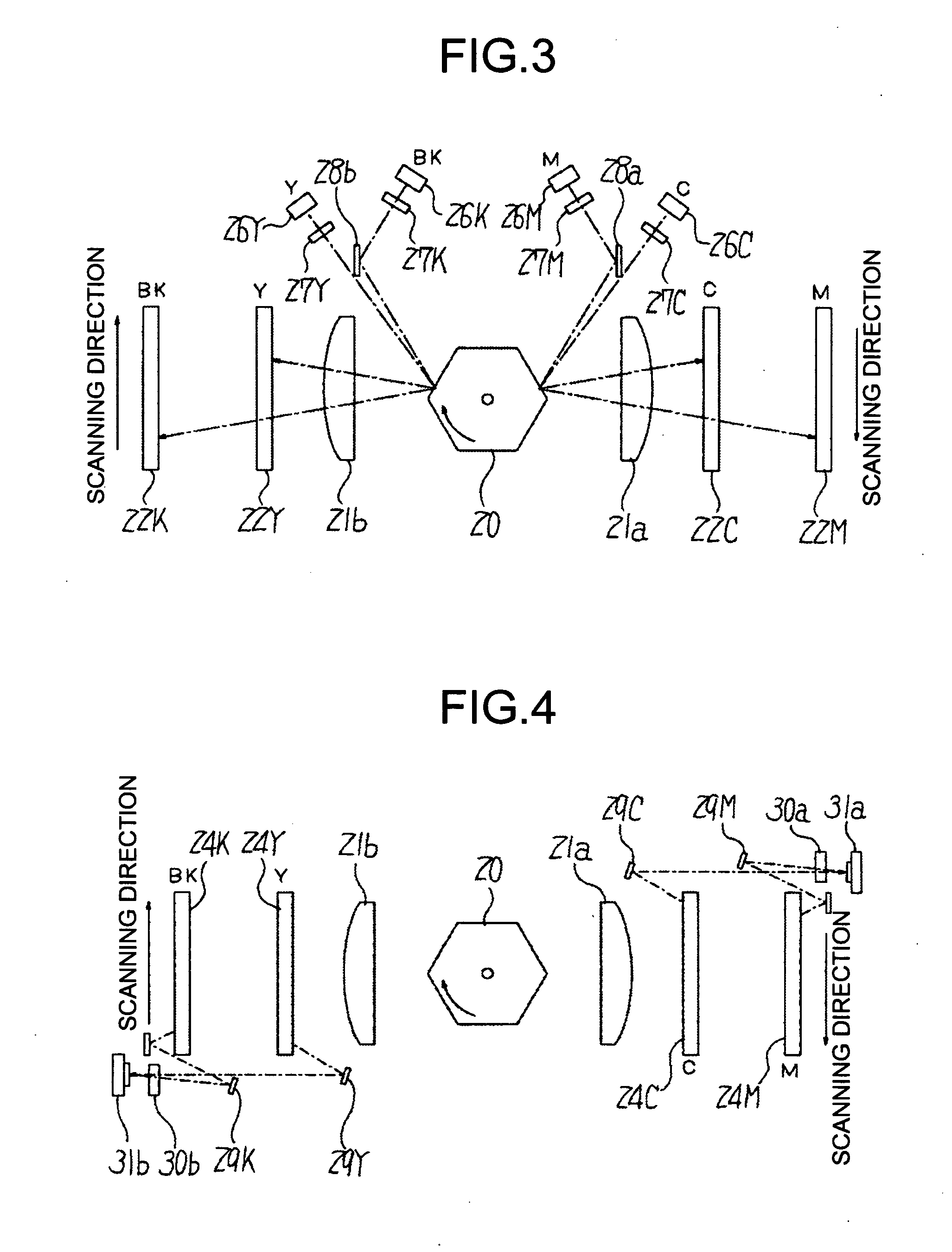
[0029]FIG. 1 is a schematic of a color image forming apparatus according to an embodiment of the present invention, FIG. 2 is a schematic of an optical writing unit for the color image forming apparatus, FIGS. 3 and 4 are plan views of the optical writing unit, and FIG. 5 is a control block diagram of the color image forming apparatus.

[0030] As shown in FIG. 1, a color image forming apparatus 101 according to the present embodiment is a tandem type. More specifically, the color image forming apparatus 101 includes four printer engines 102K, 102Y, 102C, and 102M (hereinafter, “102K to 102M”) that are arranged in a row. The printer engines 102K to 102M form images of a plurality of colors, in this case, black (K), yellow (Y), cyan (C), and magenta (M), respectively using an electrophotogra...


PUM


Abstract

A color image forming apparatus in which an engine controller outputs an operation start signal to write controllers at a timing at which a registration sensor detects a position of a sheet of transfer paper. Synchronization detection signals for colors are used to set reference positions for front edges of the colors in a main scanning direction. A write controller for a reference color outputs a write-operation start signal so as not to cut the synchronization detection signals each indicating one line for one color in the main scanning direction and line synchronization signals, into two parts in their longitudinal direction. The write-operation start signal is used to set a reference time point when the write controllers make transfer requests for image signals for the colors to an image processor.

Description

CROSS-REFERENCE TO RELATED APPLICATIONS [0001] The present document incorporates by reference the entire contents of Japanese priority document, 2004-221298 filed in Japan on Jul. 29, 2004. BACKGROUND OF THE INVENTION [0002] 1. Field of the Invention [0003] The present invention relates to a color image forming apparatus that electrophotographically forms a color image, and a process cartridge for the color image forming apparatus. [0004] 2. Description of the Related Art [0005] Tandem-type color image forming apparatuses have units each of which adjusts a timing of starting image formation for each color. Japanese Patent Application Laid-Open No. 2003-255656 discloses a technology for a tandem-type color image forming apparatus that has delay adjustment functions each of which is discretely provided for one of the colors in color images and controls a timing of starting image formation. [0006] An image forming apparatus is a device that forms an electrostatic image as an output to ...

Claims


Application Information

Patent Timeline
Patent Type & Authority Applications(United States)
IPC IPC(8): G06K15/12
CPCG03G2215/0119H04N1/1135H04N1/29H04N1/506H04N2201/04789H04N2201/04729H04N2201/04732H04N2201/04744H04N2201/04767H04N2201/04713
Inventor OHMIYA, SATOSHI
Owner RICOH KK
Learn More