Optical component molding apparatus and method thereof

a technology of optical components and molding equipment, which is applied in the field of optical component molding equipment and molding method, can solve the problems of large mold strain, large load on the mold, and failure of molding, and achieve the effects of reducing the space required for installing the molding machine, reducing the amount of molding time and resin, and saving energy and spa

Active Publication Date: 2006-02-02
KONICA MINOLTA OPTO
View PDF10 Cites 7 Cited by
  • Summary
  • Abstract
  • Description
  • Claims
  • Application Information

AI Technical Summary

Benefits of technology

[0018] According to the present invention, the mold clamping force for bringing the molds at the movable side and fixed side into close contact with each other is within a range of 20 N to 1.5 KN. Compared with a molding machine of the 5-KN class, the space required for installing the molding machine is smaller resulting in energy saving and space saving. Accordingly, the molding time

Problems solved by technology

However, the following problems reside in the conventional molding apparatus.
Therefore, the strain of the molds is large when the molds are brought into close contact with each other and separated away therefrom.
Further, when the mold clamping force is large, the load against the molds is also large.
Therefore, the molds tend to be deformed resulting in a molding failure.
Also since a large amount of resin is required for injection, generally, the plasticization section a

Method used


Image

  • Optical component molding apparatus and method thereof
  • Optical component molding apparatus and method thereof
  • Optical component molding apparatus and method thereof

Examples


Embodiment Construction

[0041] Hereinafter, embodiments, in which the present invention is embodied, will be described in detail with reference to the accompanying drawings. This embodiment is a molding machine for a plastic lens mounted on an optical pick-up device or imaging optical system, to which the present invention is applied.

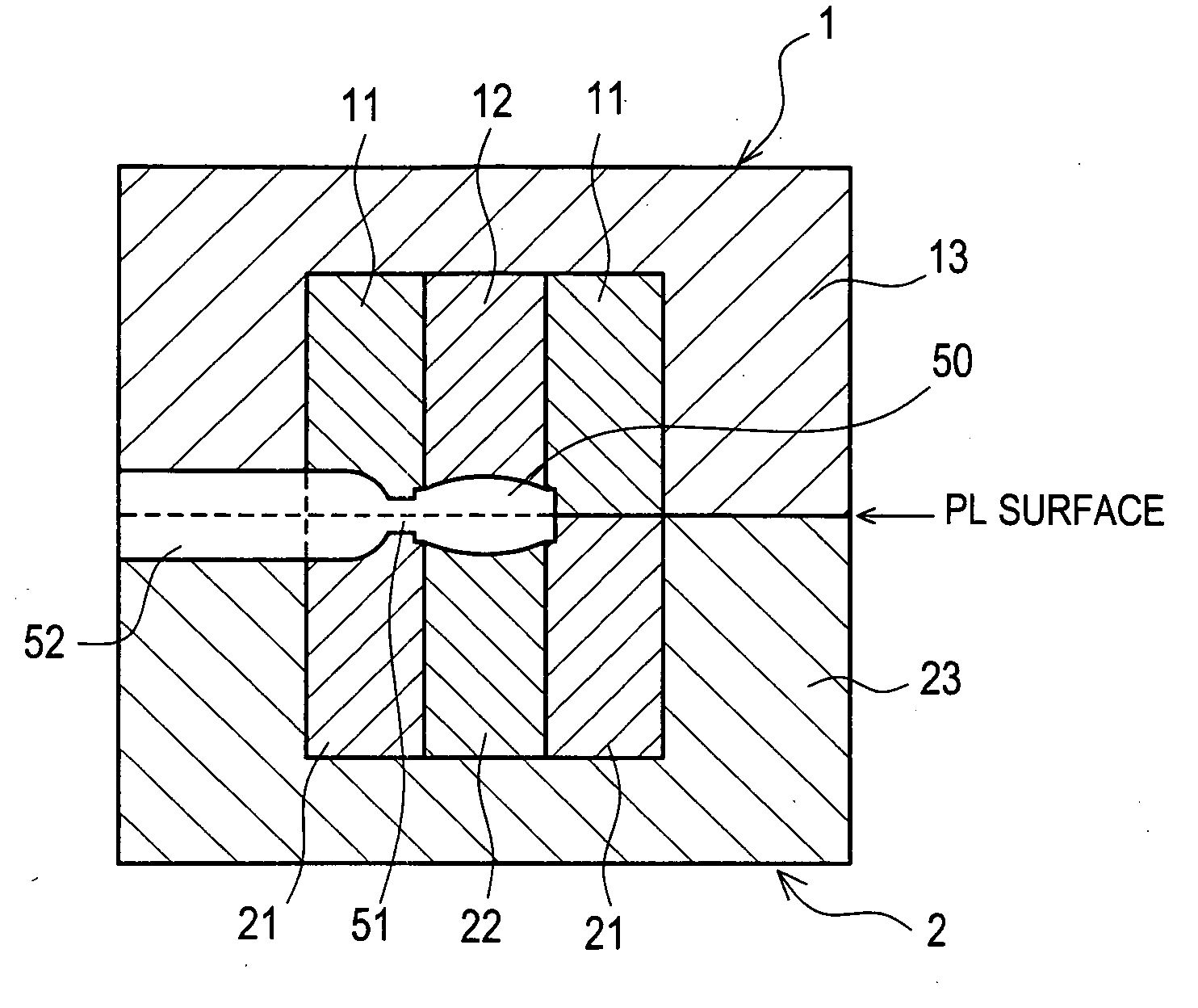
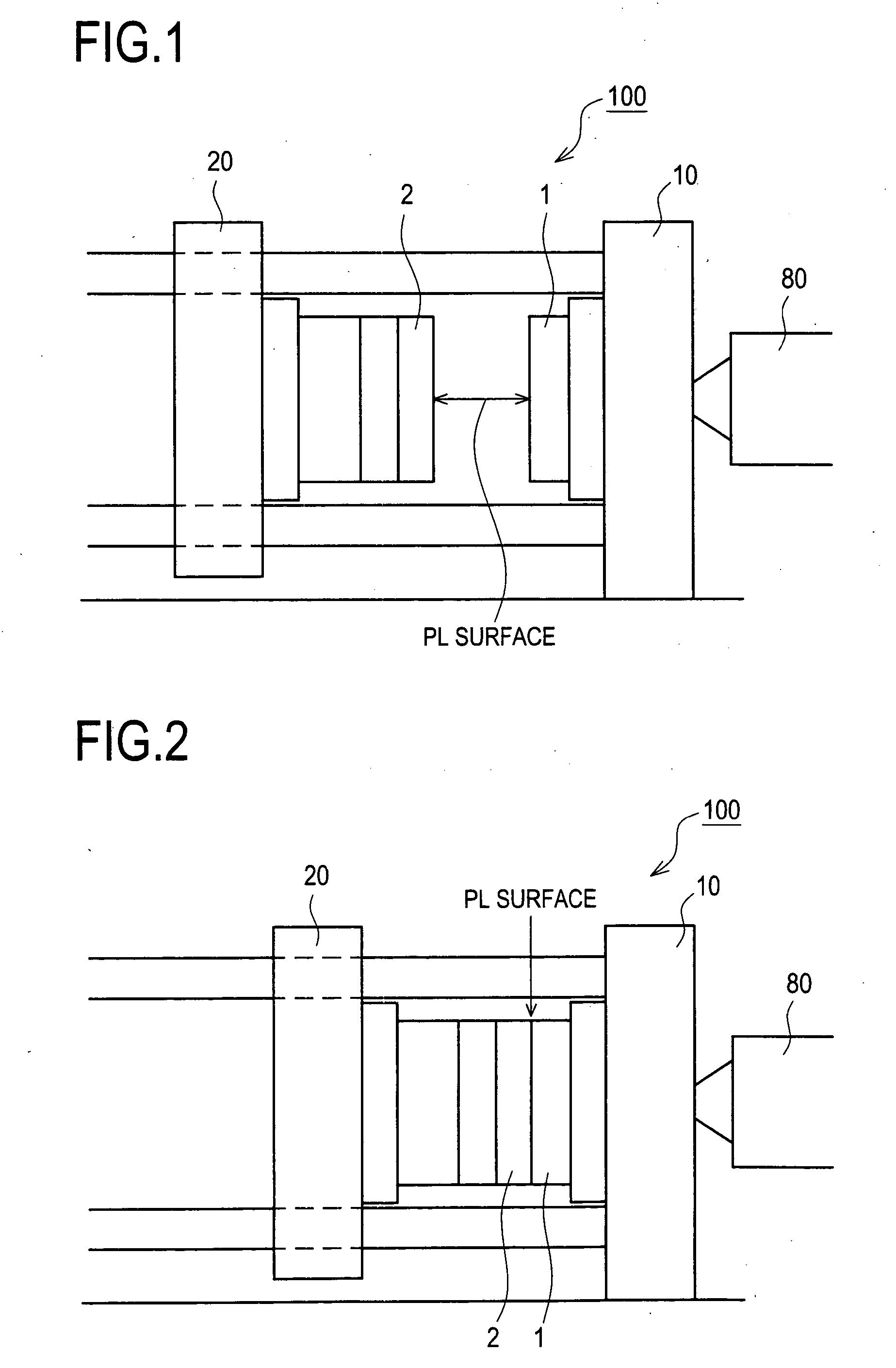
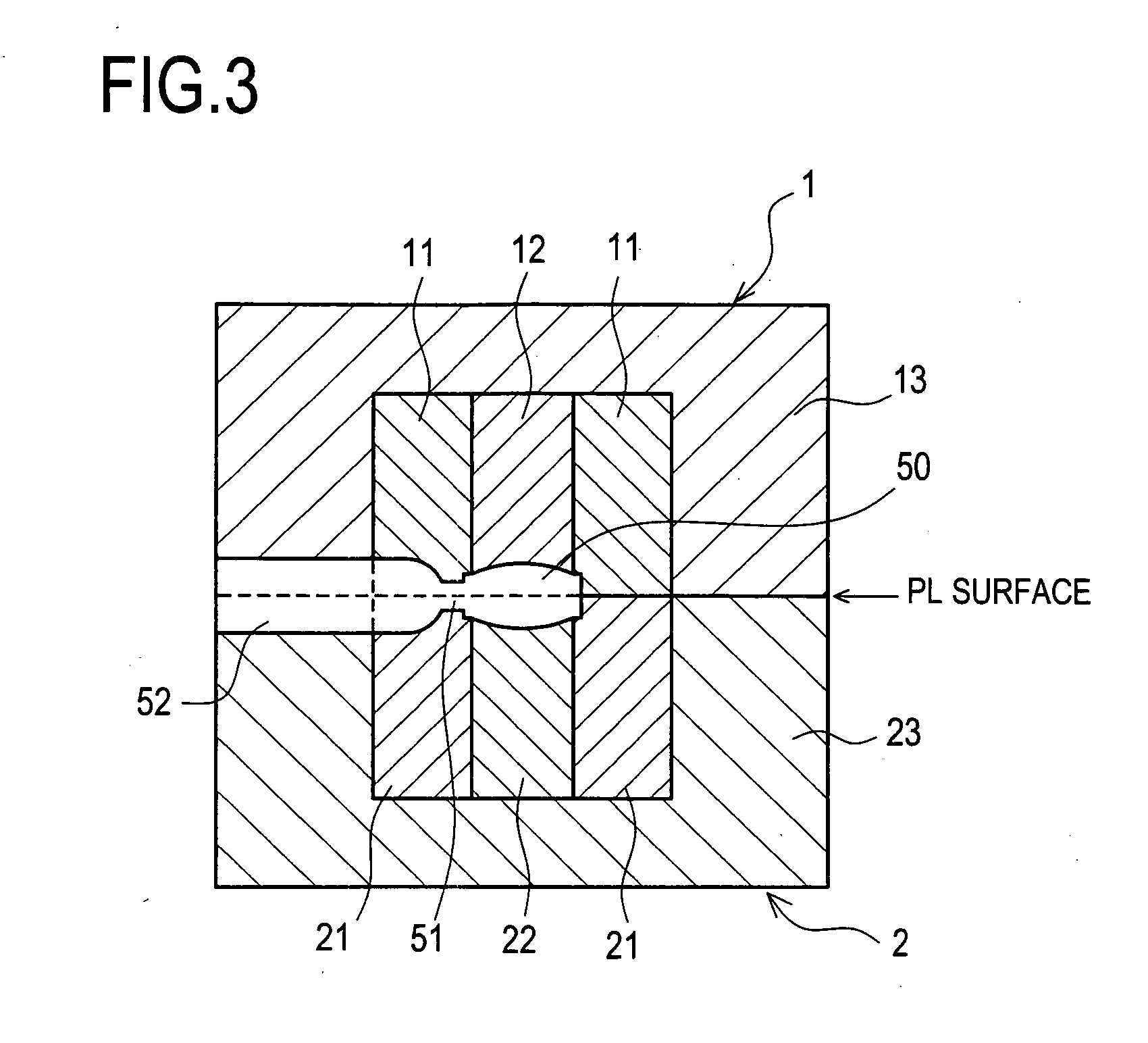
[0042]FIG. 1 and FIG. 2 are views schematically showing the structure of a molding machine 100 in accordance with the embodiment. FIG. 1 shows a state in which the molds are separated away from each other. FIG. 2 shows a state in which the molds are brought into close contact with each other. FIG. 3 schematically shows the structure of the molds of the embodiment.

[0043] In particular, the molding machine 100 for a plastic lens of the embodiment includes, as shown FIG. 1 and FIG. 2, a fixed platen 10 equipped with a fixed mold 1 and a movable platen 20 equipped with a movable mold 2, which is brought into close contact with and separated away from the fixed mold 1. The size o...


PUM

PropertyMeasurementUnit
Lengthaaaaaaaaaa
Lengthaaaaaaaaaa
Forceaaaaaaaaaa

Abstract

A molding machine includes a fixed mold and a movable mold. The molding machine is a so-called micro-molding machine which provides less than 1.5 KN of the mold clamping force for clamping the fixed mold and the movable mold. A positional shift length between both molds is preset at ±20 μm or less. Further, cavities are inserted in base molds of both molds respectively. Furthermore, cores are inserted in the cavities. The position of each cavity is adjustable with respect to each associated base mold. The position of each core is also adjustable with respect to each associated cavity. Moreover, the molding machine can simultaneously mold a plurality of optical components.

Description

CROSS-REFERENCE TO RELATED APPLICATIONS [0001] This application is based upon and claims the benefit of priority from the prior Japanese Patent Application No. 2004-225728 filed on Aug. 2, 2004, the entire contents of which are incorporated herein by reference. BACKGROUND OF THE INVENTION [0002] 1. Field of the Invention [0003] The present invention relates to an optical component molding apparatus and molding method for injection molding of a high precision optical component. In particular, the present invention relates to a molding apparatus and a method for an optical component capable of reducing the molding time period, increasing the production efficiency and reducing the cost and the like using a smaller molding machine. [0004] 2. Description of Related Art [0005] Recently, optical components such as objective lens are formed in a manner of injection molding using a plastic resin (refer to, for example, Patent Document 1 and Patent Document 2). Since, by molding optical compo...

Claims


Application Information

Patent Timeline
IPC IPC(8): D01D11/00
CPCB29C45/2606B29C45/2673B29C45/372B29L2011/0016B29C2045/2683B29D11/00413B29C2045/0034B29C45/04B29C45/76D01D11/00
Inventor MATSUMOTO, AKIHIKONAITO, ATSUSHIOKUMURA, YOSHIHIROSEKIHARA, KANJI
Owner KONICA MINOLTA OPTO
Why Eureka
Try Eureka